Figure 3-4, Installation, Installing active cards – Grass Valley NV8256-Plus v.1.2 User Manual
Page 44
34
Rev 1.2 • 20 Oct 08
3. Installation
Installing Active Cards
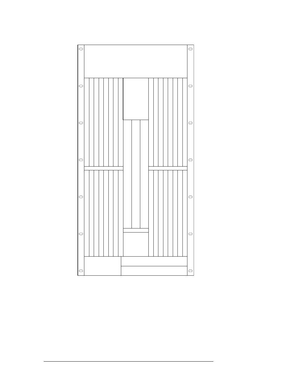
Figure 3-4. Card Locations in Router Frame (Front View)
3 On each card, press both levers inward, making sure each card is fully seated in the card guide
and slot.
4 Reinstall and close the frame front door after all cards have been installed. The door must be
closed for the router cooling system to work properly.
Control CardPrimary
OUTPUTS 129-144
OUTPUTS 145-160
OUTPUTS 161-176
OUTPUTS 177-192
OUTPUTS 193-208
OUTPUTS 209-224
OUTPUTS 225-240
OUTPUTS 241-256
INPUTS 129144
INPUTS 145160
INPUTS 161176
INPUTS 177192
INPUTS 193208
INPUTS 209224
INPUTS 225240
INPUTS 241256
OUTPUTS 116
OUTPUTS 1732
OUTPUTS 3348
OUTPUTS 4964
OUTPUTS 6580
OUTPUTS 8196
OUTPUTS 971
12
OUTPUTS 1
13128
INPUTS 116
INPUTS 1732
INPUTS 3348
INPUTS 4964
INPUTS 6580
INPUTS 8196
INPUTS 971
12
INPUTS 1
13128
MONIT
OR
FAN
CROSSPOINT
INPUTS 1-256
CROSSPOINT
(REDUNDANT)
CROSSPOINT
INPUTS 257-512
Control CardSecondary