Making alarm connections, Connections, see, Installation – Grass Valley NV8256-Plus v.1.2 User Manual
Page 58
48
Rev 1.2 • 20 Oct 08
3. Installation
Making Alarm Connections
Making Alarm Connections
The NV8256-Plus provides system alarms that notify you of a malfunction, such as when a fan or
power supply is not functioning properly. Alarms can be connected to an external alarm indicator
that displays visual cues when an alarm is activated. The NV6257 (power supply) and the NV8256-
Plus each have alarm connections. NVISION does not provide external indicator equipment, but
does provide instructions on wiring the alarm connections. See
on
Both the NV6257 and the router send status information to the router control system. For more
information on the alarm connections, see
How to Make Alarm Connections
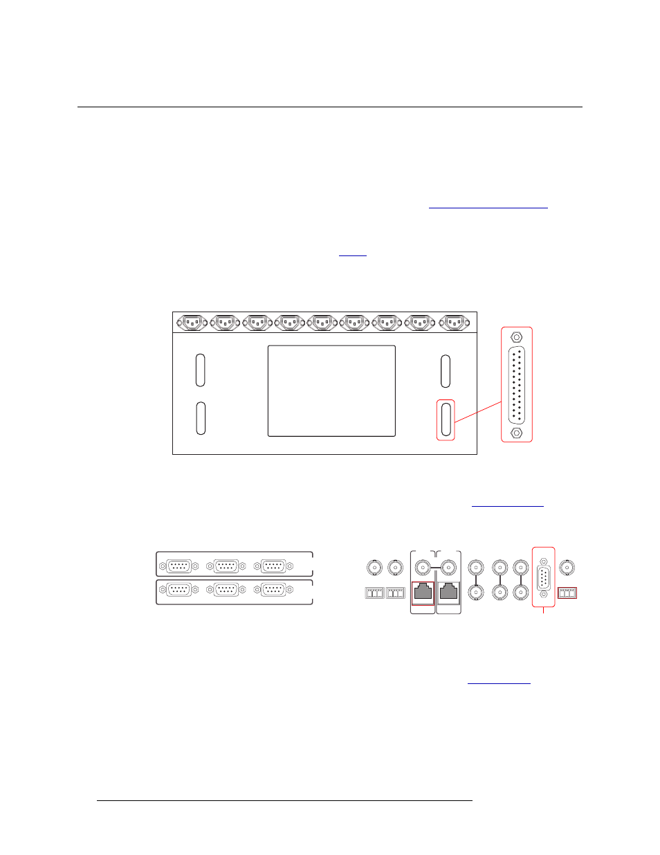
1 On the rear of the NV6257, locate the ‘Alarms’ connection, as shown in Figure 3-16.
Figure 3-16. Power Supply Alarms Connection on the NV6257 (Rear View)
2 Connect to the ‘Alarms’ connection using a DB25 connector and cable.
3 Connect the other end of the cable to an external alarm indicator. See
page 49 for information on wiring the DB25 connector.
4 On the rear of the router, locate the ‘ALARMS’ connection, as shown in Figure 3-17.
Figure 3-17. System Alarm Connection on Router (Rear View)
5 Connect to the ‘ALARMS’ connection using a DE9 connector and cable.
6 Connect the other end of the cable to an external alarm indicator. See
for information on wiring the DE9 connector.
FAN
Output
Power 1
Output
Power 2
Power
Supply
Monitors
Alarms
DB25
CTRL 1
CTRL 2
DIAG
CTRL 1
CTRL 2
DIAG
SECONDARY
CONTROL
PRIMARY
CONTROL
SEC
CTRL
PRI
CTRL
AES
REF 1
AES
REF 2
LOOP
THRU
10 B 2
10/100 BT
10 B 2
10/100 BT
VIDEO
REF 2
VIDEO
REF 1
ALARMS
TIME
CODE
NVISION
AUX BUS
LOOP
LOOP
LOOP
System Alarm
Connections