Making signal connections, Local signal connections, Installation – Grass Valley NV8256-Plus v.1.2 User Manual
Page 45: Figure 3-5. bnc connector and signal connections, Router expansion ports, Inputs 1-128
NV8256-Plus Digital Video Router • User’s Guide
35
3. Installation
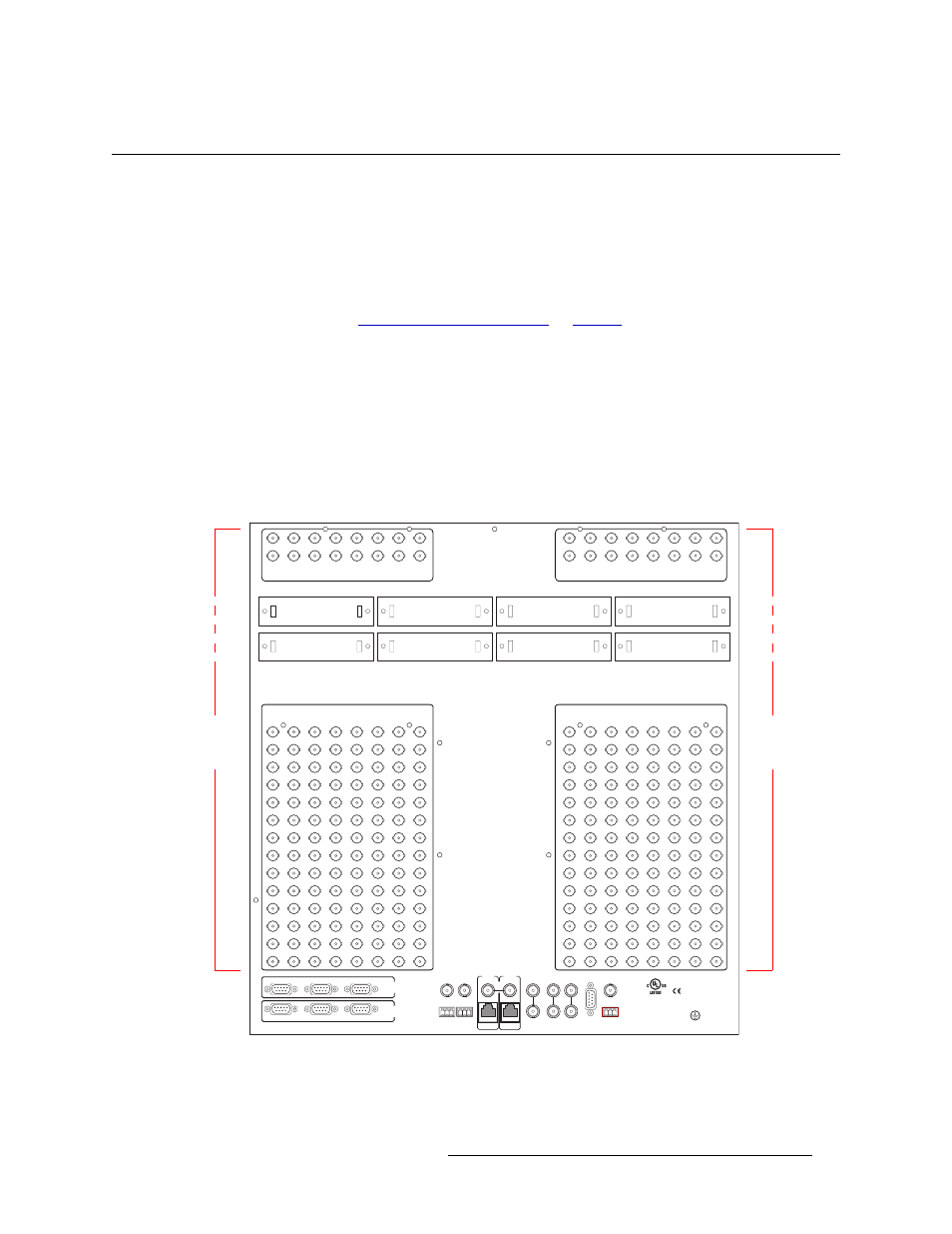
Making Signal Connections
Making Signal Connections
In order for the NV8256-Plus to properly manage incoming and outgoing signals, the I/O connec-
tions on the rear of the router must be connected to cables that receive and distribute the signals.
The NV8256-Plus contains up to 256 input connections and up to 256 output connections.
If two NV8256-Plus routers are being connected together, the signal expansion connections need to
be connected between the two routers. These connections enable each router to send local inputs to
the other router. (See
on
Local Signal Connections
Cables are connected to the I/O connections using 75
Ω BNC connectors and coaxial cable. Con-
nections must be made for each source of incoming signals and each signal distribution source.
How to Make Signal Connections
1 Locate the input connections at the rear of the router, as shown in Figure 3-5. There are 16 col-
umns of 16 BNC connections each.
Figure 3-5. BNC Connector and Signal Connections
2 For each input, connect to an input connection using a 75
Ω BNC connector and coaxial cable.
3 Connect the other end of the cable to the source of the incoming signal.
CTRL 1
CTRL 2
DIAG
CTRL 1
CTRL 2
DIAG
SECONDARY
CONTROL
PRIMARY
CONTROL
SEC
CTRL
PRI
CTRL
AES
REF 1
AES
REF 2
LOOP
THRU
10 B 2
10/100 BT
10 B 2
10/100 BT
VIDEO
REF 2
VIDEO
REF 1
ALARMS
TIME
CODE
NVISION
AUX BUS
LOOP
LOOP
LOOP
144
160
176
192
208
224
240
256
141
142
143
157
158
159
173
174
175
189
190
191
205
206
207
221
222
223
237
238
239
253
254
255
138
139
140
154
155
156
170
171
172
186
187
188
202
203
204
218
219
220
234
235
236
250
251
252
137
136
135
134
133
153
152
151
150
149
169
168
167
166
165
185
184
183
182
181
201
200
199
198
197
217
216
215
214
213
233
232
231
230
229
249
248
247
246
245
INPUTS 385 - 448
INPUTS 449 - 512
INPUTS 129-256
132
131
148
147
164
163
180
179
196
195
212
211
228
227
244
243
8
2
1
-
1
S
T
U
P
N
I
6
5
2
-
9
2
1
S
T
U
P
N
I
ACTIVE LOOPTHRU
OF INPUTS 129 - 192
ACTIVE LOOPTHRU
OF INPUTS 193 - 256
130
129
146
145
162
161
178
177
194
193
210
209
226
225
242
241
ROUTER
EXPANSION
PORTS
ACTIVE LOOPTHRU
OF INPUTS 1 - 64
ACTIVE LOOPTHRU
OF INPUTS 65 - 128
34
33
50
49
66
65
82
81
98
97
114
113
INPUTS 257 - 320
INPUTS 321 - 384
2
1
18
17
INPUTS 1-128
5
4
3
21
20
19
37
36
35
53
52
51
69
68
67
85
84
83
101
100
99
117
116
115
10
11
12
13
14
9
8
7
6
26
27
28
29
30
25
24
23
22
42
43
44
45
46
41
40
39
38
58
59
60
61
62
57
56
55
54
74
75
76
77
78
73
72
71
70
90
91
92
93
94
89
88
87
86
106
107
108
109
110
105
104
103
102
122
123
124
125
126
121
120
119
118
15
16
31
32
47
48
63
64
79
80
95
96
111
112
127
128
E146905
Input
Connectors
129–256
Input
Connectors
1–128