Control system expansion connections, S, see, Control system expansion – Grass Valley NV8256-Plus v.1.2 User Manual
Page 51: Connections, Control system expansion con, Nections, Installation, Making router control system connections
NV8256-Plus Digital Video Router • User’s Guide
41
3. Installation
Making Router Control System Connections
How to Make a GSC Node Bus Connection to the Control System
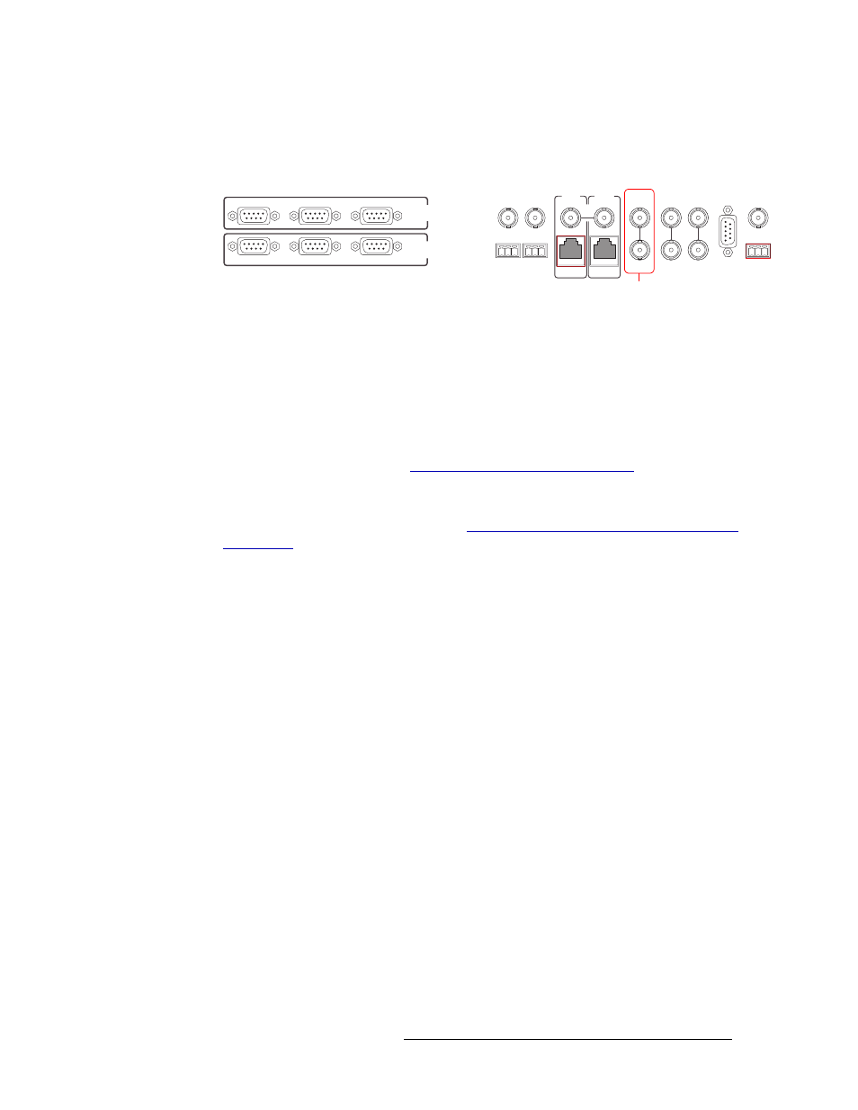
1 Locate the GSC Node Bus connection on the rear of the router, as shown in Figure 3-10. The
GSC Node Bus connection is labeled ‘NVISION AUX BUS’.
Figure 3-10. GSC Node Bus Connection to Control System (Rear View)
2 Connect to the ‘NVISION AUX BUS’ connection using a 75
Ω BNC connector and a coaxial
cable.
3 Connect the other end of the coaxial cable to the router control system.
4 On all unused ‘NVISION AUX BUS’ connections, be sure to terminate the loop-through by
installing a 75
Ω BNC terminator.
5 If you are connecting two NV8256-Plus routers together, you need to connect the control sys-
tem expansion connections. (See
Control System Expansion Connections
, following.)
Or
If the NV8256-Plus is being used as a standalone router, install 50
Ω BNC terminators on the
control system expansion connections. See
Terminating Unused Control System Expansion
Control System Expansion Connections
Control system expansion connections enable both routers to communicate with the router control
system when two NV8256-Plus routers are connected. When making control system connections,
only one router is connected directly to the router control system. This router acts as the primary
router. When making control system expansion connections, a separate connection is made from
the primary router to the secondary router. This enables the router control system to manage both
routers through the primary router connection. For simplicity, this procedure refers to each router as
the primary or secondary router.
When connecting two routers together, any unused control system expansion connections on the
secondary router must be terminated with a 50
Ω BNC connector.
The control system expansion connections are 10Base2 ports using 50
Ω BNC connectors and Cat3,
or better, coaxial cable. The BNC terminator is supplied by NVISION (12115898).
CTRL 1
CTRL 2
DIAG
CTRL 1
CTRL 2
DIAG
SECONDARY
CONTROL
PRIMARY
CONTROL
SEC
CTRL
PRI
CTRL
AES
REF 1
AES
REF 2
LOOP
THRU
10 B 2
10/100 BT
10 B 2
10/100 BT
VIDEO
REF 2
VIDEO
REF 1
ALARMS
TIME
CODE
NVISION
AUX BUS
LOOP
LOOP
LOOP
“Node Bus” Connections
to Control System