Alarm indicator equipment, Nv6257 alarms, Router alarms – Grass Valley NV8256-Plus v.1.2 User Manual
Page 59: Nv6257 alarms router alarms, Installation, Making alarm connections
NV8256-Plus Digital Video Router • User’s Guide
49
3. Installation
Making Alarm Connections
Alarm Indicator Equipment
An external alarm indicator can be created to display visual cues when a failure has occurred on the
NV6257 power supply or the NV8256-Plus router frame. LEDs can be wired to specific pins on a
DE9 or DB25 connector. Each LED indicates what specific router module has failed.
• For NV6257 alarms, see
on page 49.
NV6257 Alarms
The ‘Alarms’ connection on the rear of the NV6257 uses a DB25 connector. An “alarm” or ON
condition occurs when the connection between an alarm pin and Alarm_COM (common) opens.
The alarm turns OFF when the connection between Alarm_COM and the alarm pin closes again. If
you remove any PS6000 power supply module, the alarm circuit remains open.
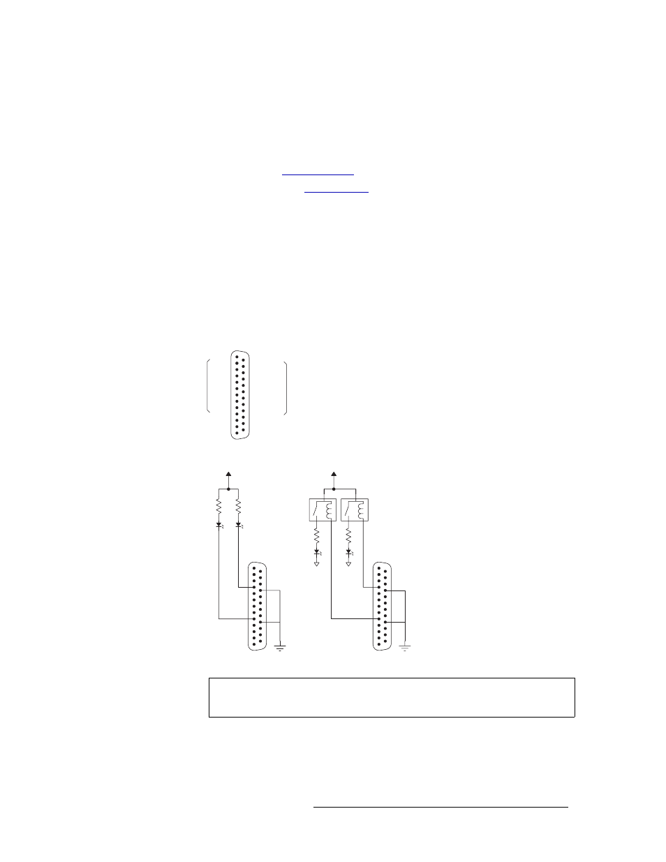
To create an indicator box, connect to the ‘Alarms’ connection using a DB25 female connector,
wiring as shown in Figure 3-18. Each pin monitors a specific function and activates a specific
alarm.
Figure 3-18. NV6257 Power Supply Alarms Connection
Router Alarms
The ‘ALARM’ connection on the rear of the NV8256-Plus uses a DE9 connector. An “alarm” or
ON condition occurs when the connection between an alarm pin and Alarm_COM (common)
Customer-supplied
relay contacts NC
Normally on, the
LEDs turn off to
indicate failure
Normally off, the
LEDs turn on to
indicate failure
External Power
30VDC max,
150mA max
GND 1
GND
14
PS1 2
PS1 COM
15
PS2 3
PS2 COM
16
PS3 4
PS3 COM
17
PS4 5
PS4 COM
18
PS5 6
PS5 COM
19
PS6 7
PS6 COM
20
PS7 8
PS7 COM
21
PS8 9
PS8 COM
22
GND 10
GND
23
GND 11
GND
24
GND 12
GND
25
GND 13
NV6257 External Power Supply Alarm, DB25, Female
Connection examples are shown below
for PS6000 power supply modules 3
and 8. Connections may be made for all
8 power supplies in the NV6257 frame.
Typical Circuit 1
Typical Circuit 2
PS3
PS8
PS3
PS8
External Ground
Caution
The power supply for the alarm circuit must not exceed 30 VDC. Load resistor
value depends on power supply voltage.