Gsc node bus control connections, Installation, Ω bnc connectors and coaxial cable – Grass Valley NV8256-Plus v.1.2 User Manual
Page 50
40
Rev 1.2 • 20 Oct 08
3. Installation
Making Router Control System Connections
How to Make an Ethernet Connection to the Router Control System
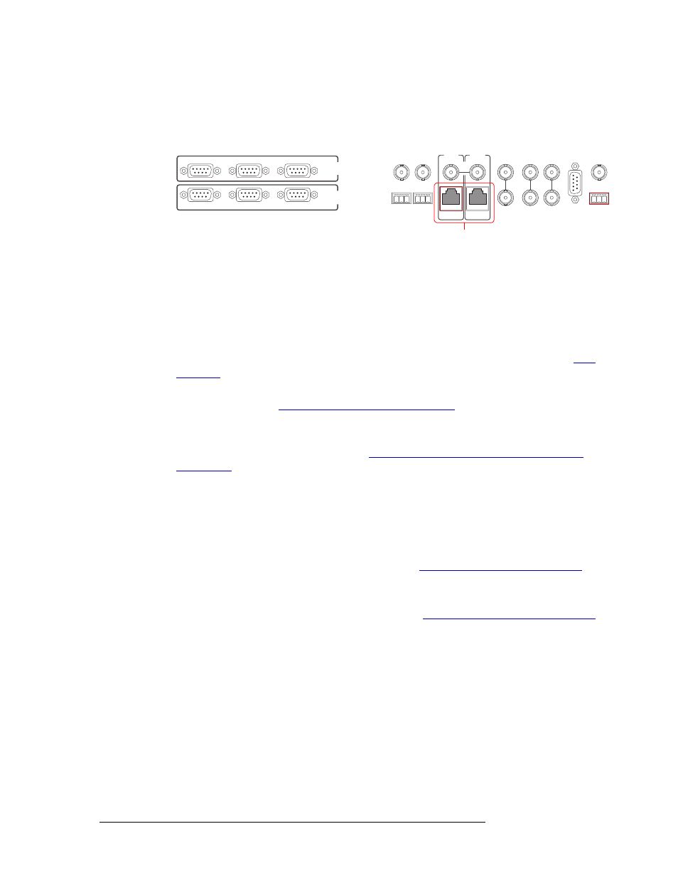
1 Locate the Ethernet connections on the rear of the router, as shown in Figure 3-9. Ethernet con-
trol connections are labeled ‘PRI CTRL’ and ‘SEC CTRL’.
Figure 3-9. Ethernet Connections to Control System (Rear View)
2 Connect to the ‘10/100 BASE T’ Ethernet connection in the ‘PRI CTRL’ section using a RJ45
connector and Cat5, or better, cable.
3 Connect the other end of the cable to an Ethernet hub or switch on the router control system
using a RJ45 connector.
4 If a secondary (optional for redundancy) control card is installed, connect to the ‘10/100 BASE
T’ Ethernet connection in the ‘SEC CTRL’ section as described in Step 2 and Step 3. See
5 If two NV8256-Plus routers are being connected together, connect the control system expan-
sion connections. (See
Control System Expansion Connections
on page 41.)
Or
If the NV8256-Plus is being used as a standalone router, install 50
Ω BNC terminators on the
control system expansion connections. See
Terminating Unused Control System Expansion
GSC Node Bus Control Connections
Some third-party router control systems require a GSC Node Bus connection to connect the router
to the router control system. The NV8256-Plus has one GSC Node Bus connection, labeled ‘NVI-
SION AUX BUS’. The connection is shared by both the primary and secondary control cards. For a
detailed description of the GSC Node Bus connection, see
GSC Node Bus Control Connections
To use the GSC Node Bus connection, an optional module must be installed on each control card.
For details, contact NVISION. For contact information, see
Technical Support Contact Information
The GSC Node Bus connection uses 75
Ω BNC connectors and coaxial cable.
CTRL 1
CTRL 2
DIAG
CTRL 1
CTRL 2
DIAG
SECONDARY
CONTROL
PRIMARY
CONTROL
SEC
CTRL
PRI
CTRL
AES
REF 1
AES
REF 2
LOOP
THRU
10 B 2
10/100 BT
10 B 2
10/100 BT
VIDEO
REF 2
VIDEO
REF 1
ALARMS
TIME
CODE
NVISION
AUX BUS
LOOP
LOOP
LOOP
Ethernet Connections
to Control System