Making diagnostic connections, Making diagnostic, Connections – Grass Valley NV8256-Plus v.1.2 User Manual
Page 52: Reconfigured. see, Terminating unused control system expansion, Installation, Ω bnc terminator
42
Rev 1.2 • 20 Oct 08
3. Installation
Making Diagnostic Connections
How to Make Control System Expansion Connections between Two Routers
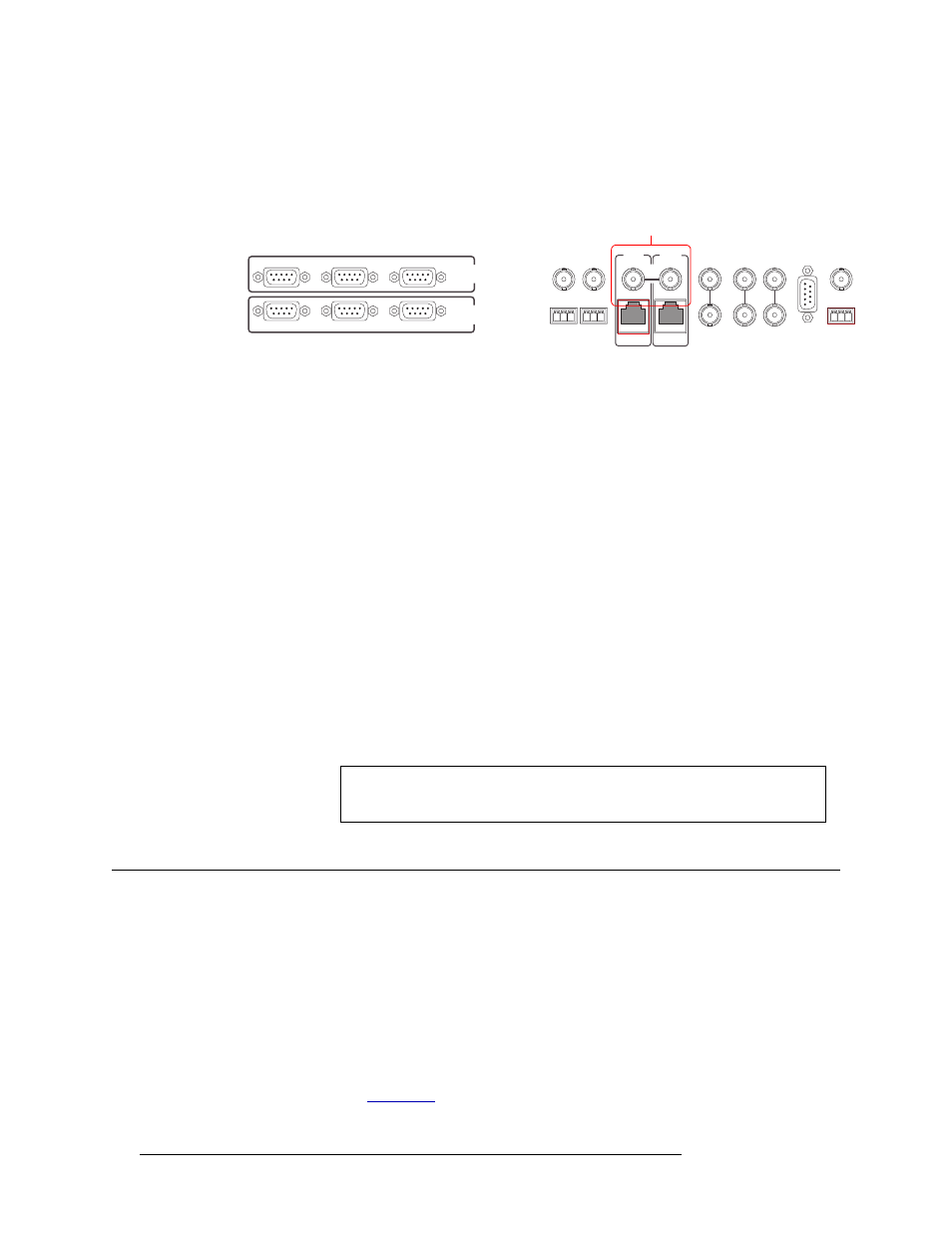
1 Locate the control system expansion connections on the rear of the two routers, as shown in
Figure 3-11. The connections are labeled ‘10 B 2’.
Figure 3-11. Expansion Connections to Control System (Rear View)
2 On the primary router (the router directly connected to the control system), connect to the ‘10 B
2’ BNC connection in either the ‘PRI CTRL’ or ‘SEC CTRL’ section using a 50
Ω BNC con-
nector (12115898) and 10Base2 cable.
3 Connect the other end of the cable to the ‘10 B 2’ BNC connection in either the ‘PRI CTRL’ or
‘SEC CTRL’ section on the secondary router using a 50
Ω BNC connector.
4 On all unused control system expansion BNC connections, install a 50
Ω BNC terminator.
Terminating Unused Control System Expansion Connections
All unused control system expansion connections must have terminators. Unused control system
expansion connections are terminated with a 50
Ω BNC terminator. The BNC terminator is supplied
by NVISION (1211598).
How to Terminate Unused Control System Expansion Connections
1 Locate the control system expansion connections on the rear of the router, as shown in Figure 3-
11. The connections are labeled ‘10 B 2’. See Figure 3-11.
2 On all unused control system expansion BNC connections, install a 50
Ω BNC terminator
(NVISION part number 1211598).
Making Diagnostic Connections
The diagnostic connections enable the NV8256-Plus to communicate with the UniConfig applica-
tion. UniConfig is installed on a unit, separate from the router (e.g., PC), and is used to perform
system setup tasks, and configure and monitor the router. For information about using UniConfig,
see the UniConfig User’s Guide.
Diagnostic connections are made by connecting the router to the unit running the UniConfig appli-
cation. There are two types of diagnostic connections: temporary and permanent. A temporary
diagnostic serial connection is located on the front of each control card. Permanent diagnostic serial
connections are located on the rear of the router, labeled ‘DIAG’. For a detailed description of the
serial connections, see
CTRL 1
CTRL 2
DIAG
CTRL 1
CTRL 2
DIAG
SECONDARY
CONTROL
PRIMARY
CONTROL
SEC
CTRL
PRI
CTRL
AES
REF 1
AES
REF 2
LOOP
THRU
10 B 2
10/100 BT
10 B 2
10/100 BT
VIDEO
REF 2
VIDEO
REF 1
ALARMS
TIME
CODE
NVISION
AUX BUS
LOOP
LOOP
LOOP
Expansion Connections
to Control System
Important
Terminators must be installed on all unused BNC control system expansion
connections.