Installation – Grass Valley NV8256-Plus v.1.2 User Manual
Page 57
NV8256-Plus Digital Video Router • User’s Guide
47
3. Installation
Making Monitor Connections
Monitor expansion connections are created by connecting the ‘OUT’ monitor connections on the
secondary router to the ‘IN’ monitor connections on the primary router.
How to Make Monitor Expansion Connections
1 Locate the monitor connections on the rear of the router, as shown in Figure 3-14 on page 46.
2 On the secondary router (the router that does not have direct connections to the monitoring
equipment), connect to the ‘OUT 1’ monitor connection using a 75
Ω BNC connector and coax-
ial cable.
3 Connect the other end of the cable to the ‘IN 1’ monitor connection on the primary router using
a 75
Ω BNC connector (the router with direct connections to the monitoring equipment), as
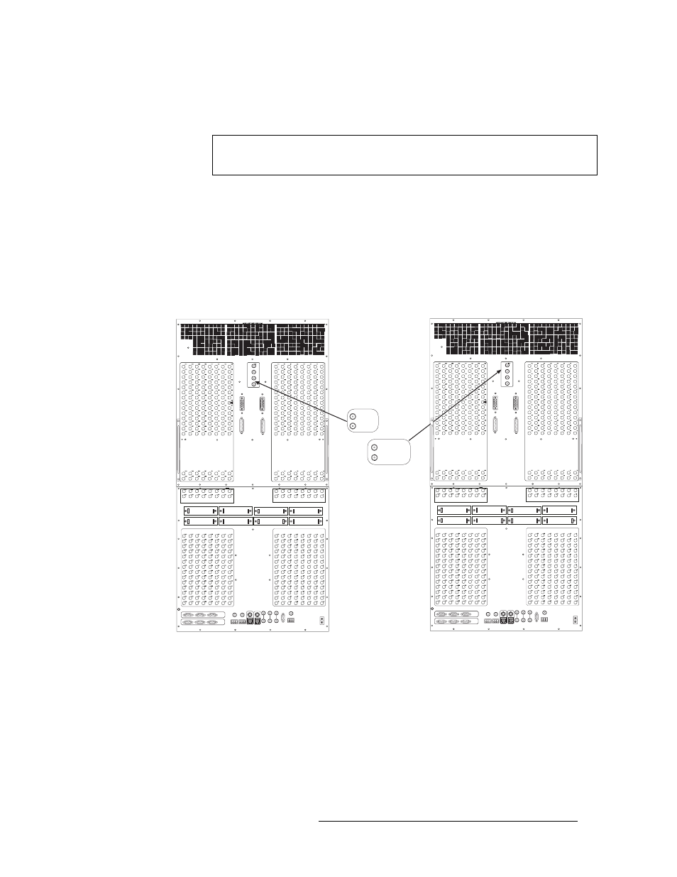
shown in Figure 3-15.
Figure 3-15. Monitor Expansion Connections Between Two Routers (Rear View)
4 On the secondary router, connect to the ‘OUT 2’ monitor connection using a 75
Ω BNC con-
nector and coaxial cable.
5 Connect the other end of the cable to the ‘IN 2’ monitor connection on the primary router using
a 75
Ω BNC connector, as shown in Figure 3-15.
Note
Unused ‘IN’ connections on the secondary router do not need to be terminated with
a BNC terminator.
OUTPUTS 129-256
OUTPUTS 1-128
INPUTS 129-256
INPUTS 1-128
ROUTER
EXPANSION
PORTS
INPUTS 1-128
INPUTS 129-256
OUTPUTS 129-256
OUTPUTS 1-128
INPUTS 129-256
INPUTS 1-128
ROUTER
EXPANSION
PORTS
INPUTS 1-128
INPUTS 129-256
Primary Router
Secondary Router
OUT 1
OUT 2
IN 1
IN 2
Connect the OUT
monitor connections
on the secondary router
to the IN
monitor connections
on the primary
router.