Middle slot functions, Minimum crosspoint cards required, Status reporting – Grass Valley NV8256-Plus v.1.2 User Manual
Page 29: Output cards, Introduction
NV8256-Plus Digital Video Router • User’s Guide
19
2. Introduction
Active Cards
• Left Slot
—
local inputs 1–256, received through local coaxial connections.
• Right Slot
—
expansion inputs 256–512, received through the expansion connections.
Middle Slot Functions
An optional, redundant crosspoint card can be installed in the middle crosspoint card slot. When a
crosspoint card is installed in this slot, four buttons located on the front of the card becomes active.
By pressing one of two designated buttons, the crosspoint card can be set to take over active control
from another crosspoint card or act as a ‘hot” backup in stand-by mode. If set to take active control,
the redundant crosspoint card takes over the current functions of the crosspoint card installed in the
left or right crosspoint card slots. If set to be a backup, the card acts as a fail-over should the pri-
mary crosspoint card be removed. For details on redundant crosspoint card set up, see
Redundant Crosspoint Card Switching
The fourth button on the redundant crosspoint card enables you to use remote control to manage the
card. For information on using remote control, see
on page 56.
Minimum Crosspoint Cards Required
The switching configuration being implemented determines the minimum number of crosspoint
cards required. For a list of required crosspoint cards required and the slot in which a crosspoint
card must be installed, see
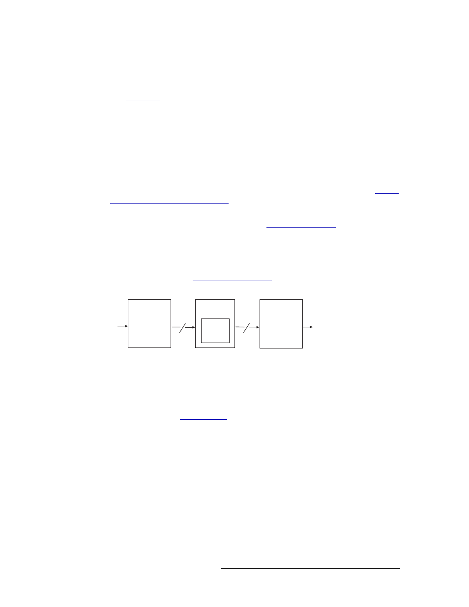
Figure 2-16 shows the flow of signals through the crosspoint card.
Figure 2-16. Crosspoint Card Block Diagram
Status Reporting
The crosspoint card includes a status reporting circuit. Five LEDs on the front of the crosspoint
card indicate the card’s status: alarm (red), power good (green), FPGA loaded (amber), good com-
munication with the control card (green) and bad communication with the control card (red). For
more information, see
on page 60.
Output Cards
The router frame can house up to 16 output cards, each processing up to 16 signals. There are two
categories of output cards: Standard and SD-to-analog. Standard output cards can manage SD,
SWB or 3Gig signals. SD-to-analog output cards convert internal SD signals to analog composite
video signals.
The following is a list of the different output cards available. Each card is listed by the function it
performs
—
standard or SD-to-analog
—
and the type of signal it manages
—
SD, SWB, 3Gig or
Motherboard
Motherboard
Input Cards
x 256
Crossbar
Switch
256 x 256
Crosspoint
Card
x 256
Output Cards