Diagnostic, Figure 2-7, Introduction – Grass Valley NV8256-Plus v.1.2 User Manual
Page 22: Module slots and rear connections, Ethernet connections to control system, Node bus” connections to control system
12
Rev 1.2 • 20 Oct 08
2. Introduction
Module Slots and Rear Connections
to alternate control systems using the same Ethernet connection via a network. For installation
instructions, see
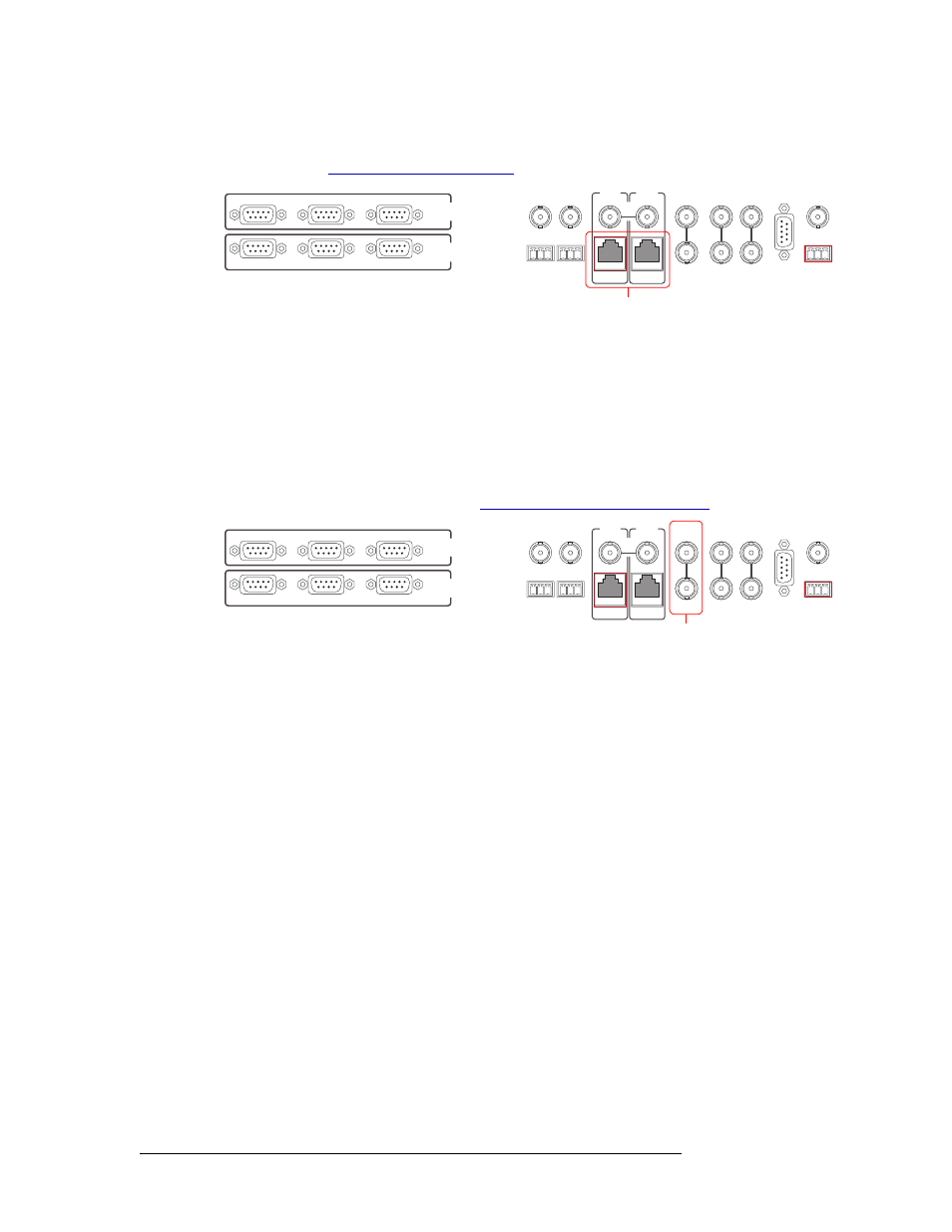
Figure 2-7. Ethernet Connections to Router Control System (Rear View)
GSC Node Bus Control Connections
Some third-party router control systems require a GSC Node Bus connection. The GSC Node Bus
connection is located on the rear of the router, as shown in Figure 2-8. The NV8256-Plus has one
GSC Node Bus connection, labeled ‘NVISION AUX BUS’. The connection is shared by both the
primary and secondary control card. To use the GSC Node Bus connection, an optional module
must be installed on each control card. For details, contact NVISION. For contact information, see
page iii. For installation instructions, see
GSC Node Bus Control Connections
Figure 2-8. GSC Node Bus Connections to Router Control System (Rear View)
Diagnostic
The diagnostic connections enable the NV8256-Plus to communicate with the UniConfig applica-
tion. UniConfig runs on a PC separate from the router and is used to perform system setup tasks,
and configure and monitor the router. For information about using UniConfig, see the UniConfig
User’s Guide.
Diagnostic connections connect the router to the PC running the UniConfig application. There are
two types of diagnostic connections: temporary and permanent. A temporary diagnostic serial con-
nection is located on the front of each control card. Permanent diagnostic connections are located
on the rear of the router, labeled ‘DIAG’, as shown in Figure 2-9. There are two permanent ‘DIAG’
ports, one primary (‘PRIMARY CONTROL’) and one secondary (‘SECONDARY CONTROL’).
The primary control connects to the primary control card. The secondary control connects to the
secondary (optional for redundancy) control card.
CTRL 1
CTRL 2
DIAG
CTRL 1
CTRL 2
DIAG
SECONDARY
CONTROL
PRIMARY
CONTROL
SEC
CTRL
PRI
CTRL
AES
REF 1
AES
REF 2
LOOP
THRU
10 B 2
10/100 BT
10 B 2
10/100 BT
VIDEO
REF 2
VIDEO
REF 1
ALARMS
TIME
CODE
NVISION
AUX BUS
LOOP
LOOP
LOOP
Ethernet Connections
to Control System
CTRL 1
CTRL 2
DIAG
CTRL 1
CTRL 2
DIAG
SECONDARY
CONTROL
PRIMARY
CONTROL
SEC
CTRL
PRI
CTRL
AES
REF 1
AES
REF 2
LOOP
THRU
10 B 2
10/100 BT
10 B 2
10/100 BT
VIDEO
REF 2
VIDEO
REF 1
ALARMS
TIME
CODE
NVISION
AUX BUS
LOOP
LOOP
LOOP
“Node Bus” Connections
to Control System