Local monitor connections, Monitor expansion connections, Monitor – Grass Valley NV8256-Plus v.1.2 User Manual
Page 56: Expansion connections, Installation, Making monitor connections, Figure 3-14. monitor connections (rear view), Monitors
46
Rev 1.2 • 20 Oct 08
3. Installation
Making Monitor Connections
from each output card in the router. By connecting monitoring equipment to the monitor connec-
tions, the quality of signals being distributed from the router can be verified.
If connecting two NV8256-Plus routers together, only one router is connected directly to the moni-
toring equipment. This router acts as the primary router. Monitor expansion connections are then
made between the primary router and the secondary, connected router. This enables the monitoring
equipment to see both routers through the monitor connections on the primary router. (See
on page 46.)
Local Monitor Connections
There are two monitor connections: ‘OUT 1’ and ‘OUT 2’, located on the rear of the router. Each
connection can be configured to match a level set up in the control system. Depending on how lev-
els are configured, ‘OUT 1’ and ‘OUT 2’ can each monitor one signal type: SD, SWB or 3Gig. For
more information, see
How to Make Monitor Connections
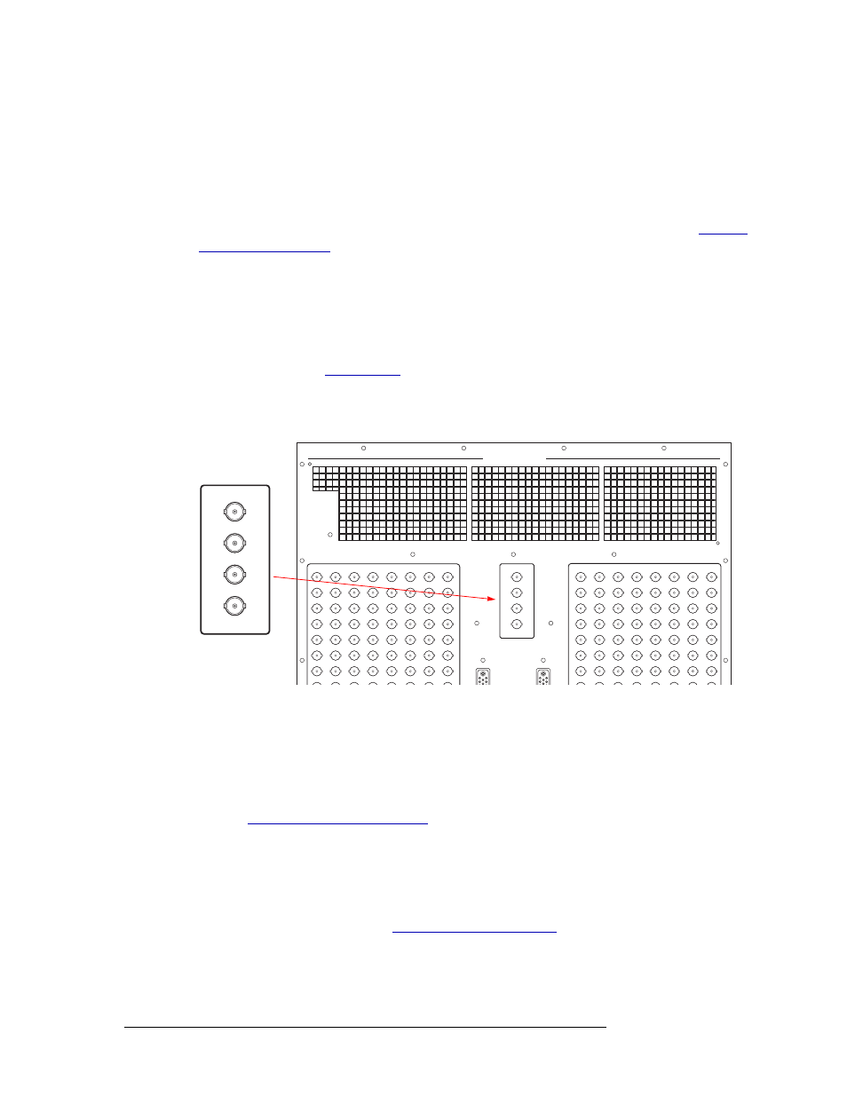
1 Locate the monitor connections on the rear of the router, as shown in Figure 3-14.
Figure 3-14. Monitor Connections (Rear View)
2 Connect to the ‘OUT 1’ monitor connection using a 75
Ω BNC connector and coaxial cable.
3 Connect the other end of the cable to the monitoring equipment being used to monitor outgoing
signals.
4 Connect to the ‘OUT 2’ monitor connection using a 75
Ω BNC connector and coaxial cable.
5 If connecting two NV8256-Plus routers together, connect the monitor expansion connections.
Monitor Expansion Connections
If two NV8256-Plus routers are connected together, monitor expansion connections need to be con-
nected between the routers. One router acts as the primary router. This router is directly connected
to the monitoring equipment. (See
on page 45.) The secondary, con-
nected router is connected to the primary router’s monitor expansion connections. This enables you
to monitor signals for both routers through the primary router’s connection to the monitoring equip-
ment. For simplicity, this procedure refers to each router as the primary or secondary router.
AIR EXHAUST KEEP CLEAR 6" MIN
IN 1
IN 2
OUT 1
OUT 2
MONITORS
POWER
POWER
1
17
33
49
65
81
97
113
2
18
34
50
66
82
98
114
8
7
6
5
4
3
24
23
22
21
20
19
40
39
38
37
36
35
56
55
54
53
52
51
72
71
70
69
68
67
88
87
86
85
84
83
104
103
102
101
100
99
120
119
118
117
116
115
129
145
161
177
193
209
225
241
130
146
162
178
194
210
226
242
136
135
134
133
132
131
152
151
150
149
148
147
168
167
166
165
164
163
184
183
182
181
180
179
200
199
198
197
196
195
216
215
214
213
212
211
232
231
230
229
228
227
248
247
246
245
244
243
A
A
IN 1
IN 2
OUT 1
OUT 2
MONITORS