Grass Valley DD10 part 1 User Manual
Page 12
2.1 Source Selection Panel
Diamond digital DD10
6
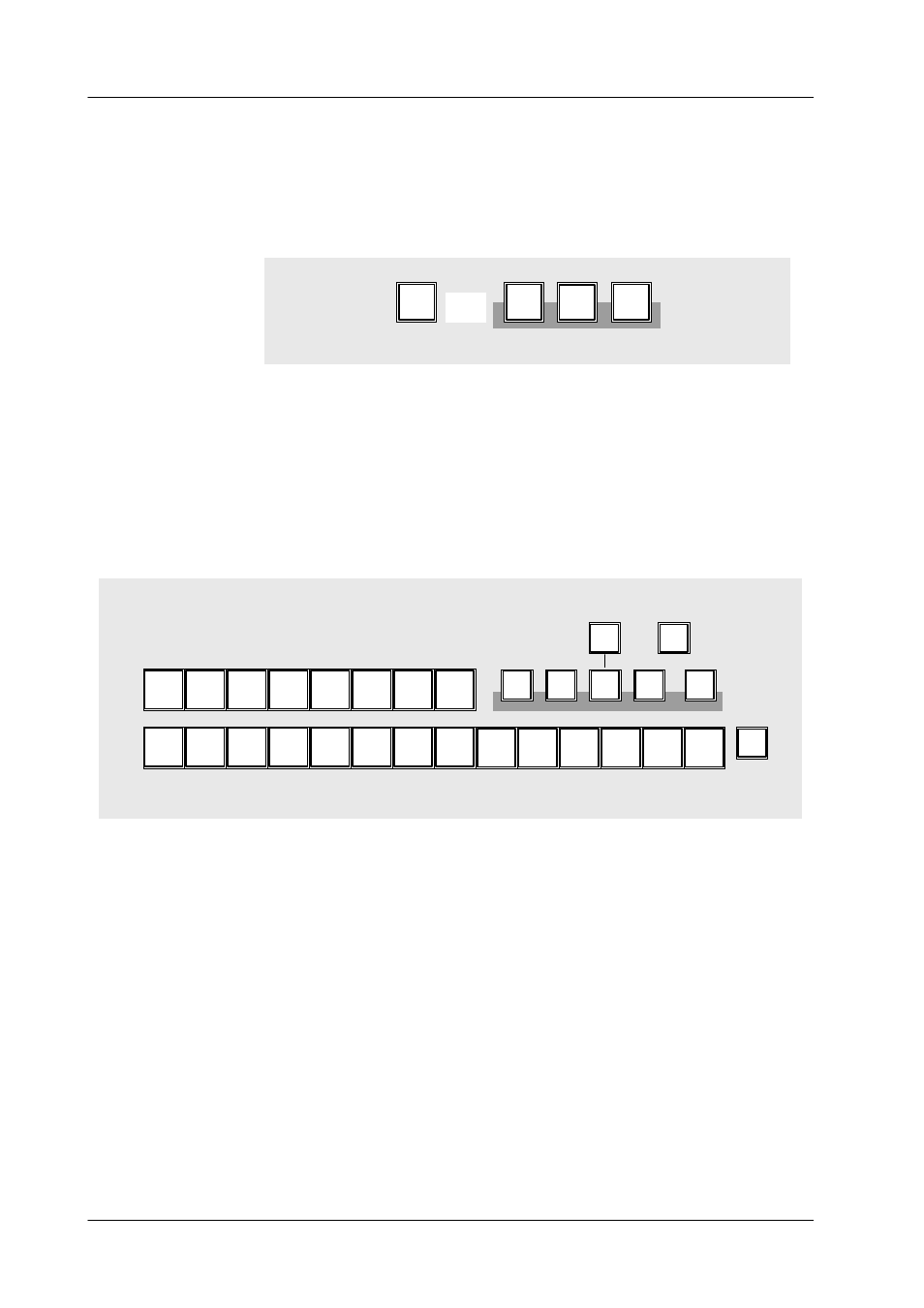
Key Bus
The Key Bus serves the selection and indication of key and fill signals. The key row
is available to all 3 keyers of the switcher. The green displays Key 1, Key 2 (red
for ON AIR) and DSK show the keyer that the key bus is currently assigned to.
Assignment of the key bus is made with Key 1, Key 2 or DSK on the Keyers panel
or by selecting the keyers with the next transition keys Key 1 or Key 2 on the Transi-
tion panel.
Cut
DSK
Key
on
Key
Key
1
2
Details about key control are contained in the sections Keyers Panel and Transi-
tion Panel.
2nd Delegation
The 2nd key enables selection of further signals (e.g. video store) in addition to the
12 directly selectable sources (e.g. frame store). The 2nd key will light when
pressed. The currently applicable key assignment is shown by the key caps of the
upper AUX bus.
2nd
5
4
3
2
1
8
7
6
Video
16
15
14
13
PGM
PVW
Clean
11
10
9
Black
BGD
12
Aux1
Aux2
Aux3
DVE
Ext
Aux
Store
Video
Store
Matte
Input
Corr
On Air
The buses involved in the output picture are indicated by the red displays On air
to the right of the program and preset bus and by the red displays Key 1, Key 2 and
DSK next to the key bus.
Asynchronous sources
Asynchronous picture signals are marked by blinking of the On air display.
Note:
Asynchronous picture signals are instantaneously switched through by
the switcher. An interference-free operation of the succeeding units is not
always ensured.
See also REPL ASYNC in the CONFIG E BOX menu.