Connecting the switch to the network, Introduction, Connection procedure – H3C Technologies H3C S12500 Series Switches User Manual
Page 59
49
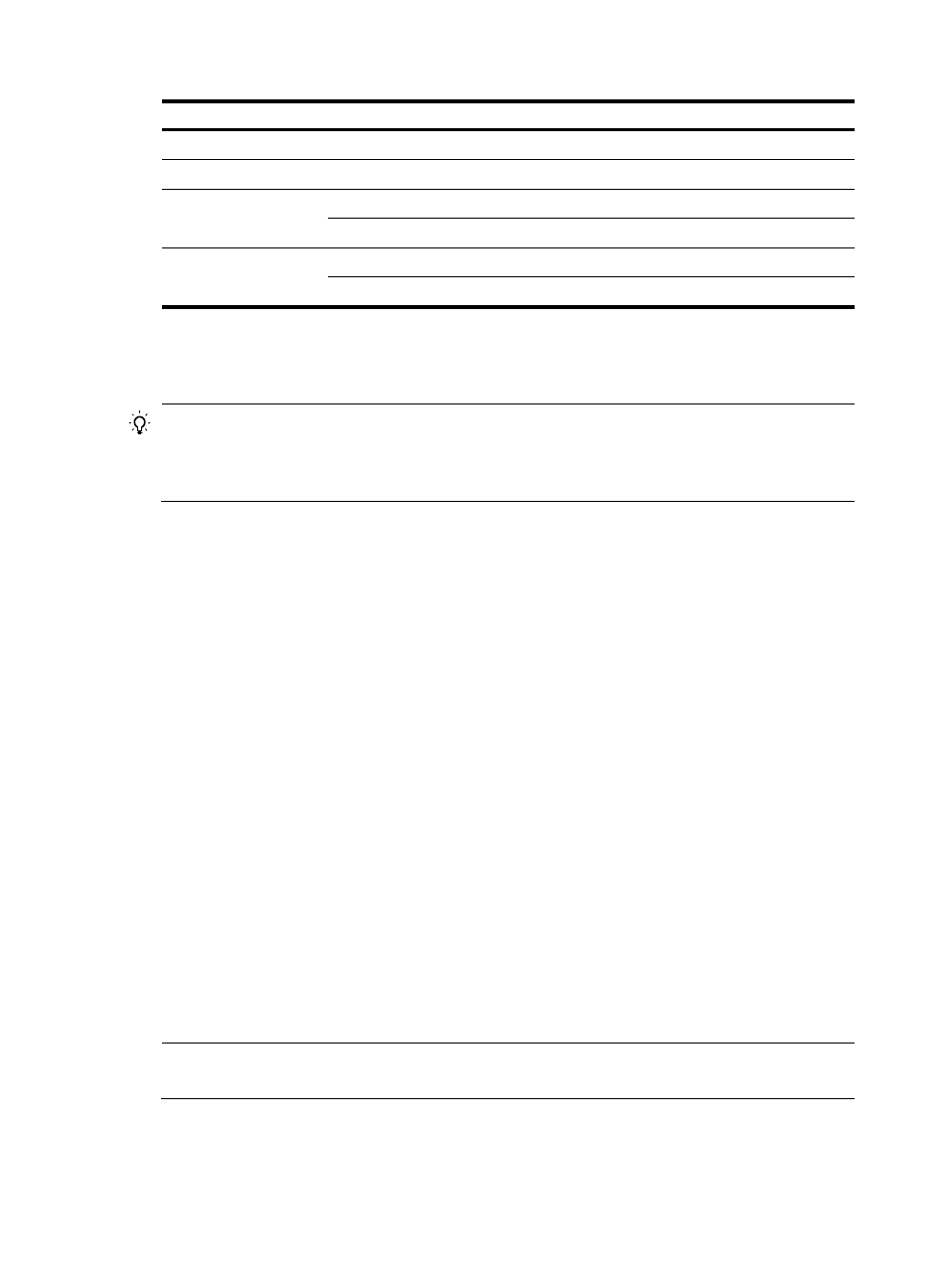
Module LED
Status
LPU
RUN (red and green)
Flashing green
Switching fabric module RUN (red and green)
Flashing green
Power monitoring
module
RUN (green)
Flashing
ALM (red)
Off
Fan
RUN (green)
Flashing
ALM (red)
Off
Connecting the switch to the network
TIP:
After connecting the switch to the network, you can use the ping or tracert command to check the
interoperability between the switch and network. For more information, see
H3C S12500 Routing Switch
Series Network Management and Monitoring Command Reference.
Connecting the switch to the network through the AUX port
You need an AUX cable when configuring a switch with the remote modem dial-up approach.
Introduction
An AUX cable is an 8-core shielded cable. At one end of the cable is an RJ-45 connector and at the other
end is a DB-9 (male) connector. Plug the RJ-45 connector into the AUX port of the switch and the DB-9
(male) connector into the DB-9 (female) port of the modem. An AUX cable is the same as a console cable.
For more information, see
and
Connection procedure
To connect the AUX port:
1.
Plug the RJ-45 connector of the AUX cable into the AUX port of the switch.
2.
Plug the DB-9 (male) connector at the other end into the serial port of the modem.
Connecting the switch to the network through a copper Ethernet
port
The 10/100/1000Base-T copper ports of the switch support MDI/MDI-X auto-sensing. They are
connected to the network through category-5 or above twisted pairs that are equipped with RJ-45
connectors.
NOTE:
No Ethernet twisted pair cables are shipped with the switch. Prepare them by yourself.
Connection procedure
To connect a 10/100/1000Base-T port: