Installation procedures – H3C Technologies H3C S12500 Series Switches User Manual
Page 33
23
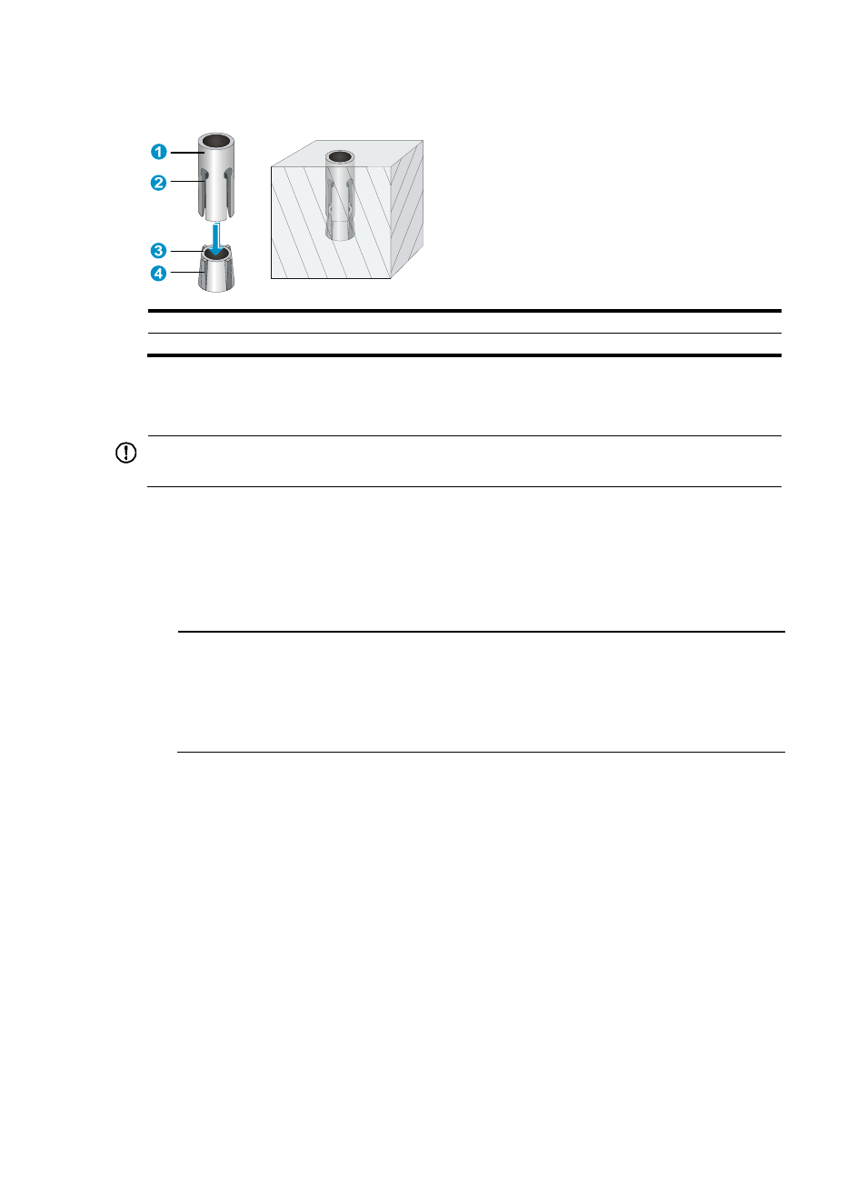
Figure 19 Installing the wall anchor
(1) Shank
(2) Groove
(3) Plug
(4) Spade-shaped wedge
Installation procedures
IMPORTANT:
Allow 0.8 m (2.62 ft) of clearance around the switch for heat dissipation.
To install the switch:
1.
Hold the two sides of the switch and steadily move the switch to the workbench.
2.
Lift the switch a little higher than the workbench and put it on the workbench.
3.
(Optional.) Install the cable management brackets on both sides of the switch and fasten the
screws, as shown in
NOTE:
The circled areas in
are the cable management bracket installation holes.
•
An S12504 switch has two columns of installation holes. You can choose either column for
installation.
•
An S12508 or S12518 switch has one column of installation holes.
- H3C S12500X-AF Series Switches (3 pages)
- H3C S12500X-AF Series Switches (3 pages)
- H3C S12500X-AF Series Switches (53 pages)
- H3C S12500 Series Switches (19 pages)
- H3C MSV 50 (8 pages)
- H3C S12500 Series Switches (21 pages)
- H3C S9500E Series Switches (4 pages)
- H3C S7500E Series Switches (3 pages)
- H3C WA2200 Series WLAN Access Points (42 pages)
- H3C S12500-X Series Switches (8 pages)
- H3C SR6600 (64 pages)
- H3C S9500E Series Switches (36 pages)
- H3C WA3600 Series Access Points (237 pages)
- H3C S9500E Series Switches (270 pages)
- H3C MSR 900 (249 pages)
- H3C S12500 Series Switches (170 pages)
- H3C MSR 900 (96 pages)
- H3C MSR 900 (443 pages)
- H3C MSR 900 (468 pages)
- H3C S9500E Series Switches (32 pages)
- H3C S9500E Series Switches (241 pages)
- H3C S12500 Series Switches (39 pages)
- H3C S6800 Series Switches (59 pages)
- H3C LSBM1WCM2A0 Access Controller Module (197 pages)
- H3C S10500 Series Switches (27 pages)
- H3C LSBM1WCM2A0 Access Controller Module (226 pages)
- H3C S6300 Series Switches (188 pages)
- H3C MSR 900 (410 pages)
- H3C MSR 900 (239 pages)
- H3C WA3600 Series Access Points (394 pages)
- H3C S10500 Series Switches (2 pages)
- H3C S10500 Series Switches (2 pages)
- H3C S10500 Series Switches (2 pages)
- H3C S10500 Series Switches (2 pages)
- H3C S10500 Series Switches (2 pages)
- H3C S10500 Series Switches (2 pages)
- H3C S10500 Series Switches (2 pages)
- H3C S10500 Series Switches (1 page)
- H3C S7500E Series Switches (19 pages)
- H3C S7500E Series Switches (115 pages)
- H3C S6300 Series Switches (58 pages)
- H3C S6300 Series Switches (208 pages)
- H3C S6300 Series Switches (251 pages)
- H3C S10500 Series Switches (140 pages)