Hardware overview, 1 local bus, Local bus – Sundance SMT310Q User Manual
Page 9: Figure 3 - smt310q block diagram, Local bus the smt310q uses a local bus
Version 2.1
Page 9 of 55
SMT310Q User Manual
3. Hardware Overview
JTAG
TIM 1
TIM 2
TIM 3
TIM 4
SRAM
COMPORT CONNECTION MATRIX
Connection
control
HOST
comport
HOST
SDB
CBuf
FMS
FMS
FMS
Buffered External
JTAG connector
JTAG In, Internal
JTAG Out, Internal
GLOBAL BUS
Buffered
Comport
V
3
P
C
I B
rid
ge
7
8-bit
8-bit
8-bit
8-bit
16-bit
32-bit
8-bit
6 ports
6 ports
6 ports
6 ports
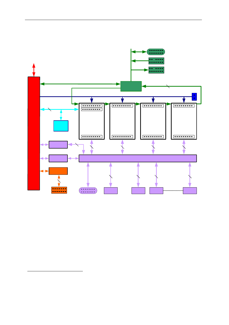
Figure 3 - SMT310Q Block Diagram
3.1
Local Bus
The SMT310Q uses a Local Bus
to control transfers amongst the various
resources. The bus has a 33MHz clock that is available on the CLKIN pin of the
Master TIM site. The TIM in this site should be set to select the local bus clock
in preference to its own oscillator to allow it to synchronise accesses across the
PCI Bridge. Details of this can usually be found in the TIM documentation under
“Global Bus Control Register”.
2
The Local Bus is not shown explicitly in the SMT310Q block diagram.