Jtag controller – Sundance SMT310Q User Manual
Page 21
Version 2.1
Page 21 of 55
SMT310Q User Manual
6. JTAG Controller
The SMT310Q has an on board Test Bus Controller (TBC), an SN74ACT8990 from
Texas Instruments. The TBC is controlled from the PCI bus giving access to the on-
site TIMs and any number of external TIMs. Please refer to the Texas Instruments
data sheet for details of this controller. The TBC is accessed in I/O space BAR1
offset 80
16
.
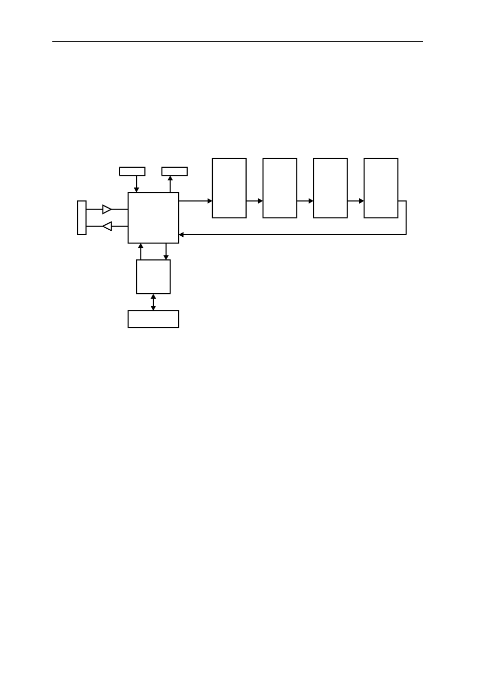
Test Bus
Switching
Matrix
Test Bus
Controller
PCI bridge
Site 1
Site 2
Site 3
Site 4
Buffers
Buffered
JTAG
Connector
XDS-510
compatible
JTAG in
XDS-510
compatible
JTAG out
Figure 6: TBC Data Routing
The SMT310Q can operate in two TBC modes; Master mode and Slave mode. In
Master mode, the Test Bus Controller on the SMT310Q drives the JTAG scan chain
through the TIM sites on the SMT310Q. If any or all the sites are not populated with a
TIM then the module’s SENSE signal is used to enable a tri-state buffer connecting
TDI and TDO (JTAG Data In and Data Out) on the specific site, maintaining the
integrity of the JTAG data path. This switching is automatic. The Buffered External
JTAG Connector J5 is intended to connect to a JTAG device external to the system
chassis. When the SMT310Q is in master mode, the buffered JTAG connector acts
as a master and is to be connected to JTAG slaves. The un-buffered JTAG out (XDS-
510) Header J11 is for use with JTAG slaves within the system chassis. When either
of these connectors is connected to a JTAG slave device, the SMT310Q
automatically detects the device and routes the test data accordingly. Master mode is
selected with a jumper in location A on J3.
When the SMT310Q is configured in Slave mode, the TBC on the SMT310Q is
disabled, as the TBC is assumed to be on another device connected to the
SMT310Q. If using a TBC device within the same system chassis, the connection
can be made using the XDS-510 compatible connector J14.