Sundance SMT310Q User Manual
Page 27
Version 2.1
Page 27 of 55
SMT310Q User Manual
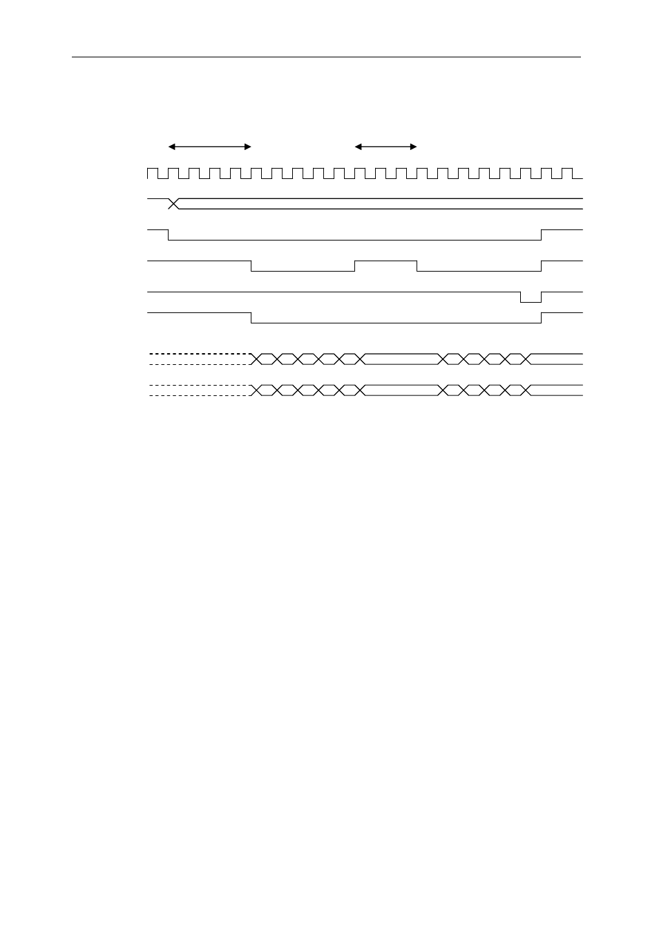
In the timing diagram below all signals change relative to the rising LCLK signal.
This signal is the H1 clock signal of the DSP when using the DSP global bus in
synchronous mode.
TIMReq FIFO
Full
LCLK
STRB1
RDY1
STAT0
AE/DE
A[30..0]
D[31..0]
STAT
Figure 8: Timing diagram for DSP local bus access
LCLK Period =30ns, frequency is 33MHz.
The DSP initiates a global bus R/W by asserting the STRB1 low and STAT[1:3]
change (see the TIM Spec for details of STAT[1..3]). Once the arbitration unit
detects this, it waits for the last cycle of the Local bus to be completed by the
PCI bridge, before allowing the DSP to become Bus Master. Once the DSP is
Master the arbitration unit drives AE and DE low to enable the DSP’s address
and data lines. RDY1 is driven low by the arbiter to indicate to the DSP, on the
next rising LCLK, that the data packet has been transferred. If the input FIFO
(256 words deep) becomes full, the arbitration logic de-asserts the RDY1 signal
to indicate a hold-off state.
Once the data have been transferred from the FIFO to the PCI bus, RDY1 is re-
asserted to continue the transfer. Asserting STAT0 low indicates the end of the
burst access. If RDY1 is not active then STAT0 should remain asserted until
ready is asserted and the final data transaction has been completed.
It is possible for a deadlock condition to arise if the PCI bus is trying to read
from the SMT310Q resources while the DSP is reading from the PCI Bus. If
this happens, the arbitration unit gives the PCI bridge device priority and
services the HOST PCI access before giving bus ownership back to the DSP.