Jtag device, Slave connector – Sundance SMT310Q User Manual
Page 47
Version 2.1
Page 47 of 55
SMT310Q User Manual
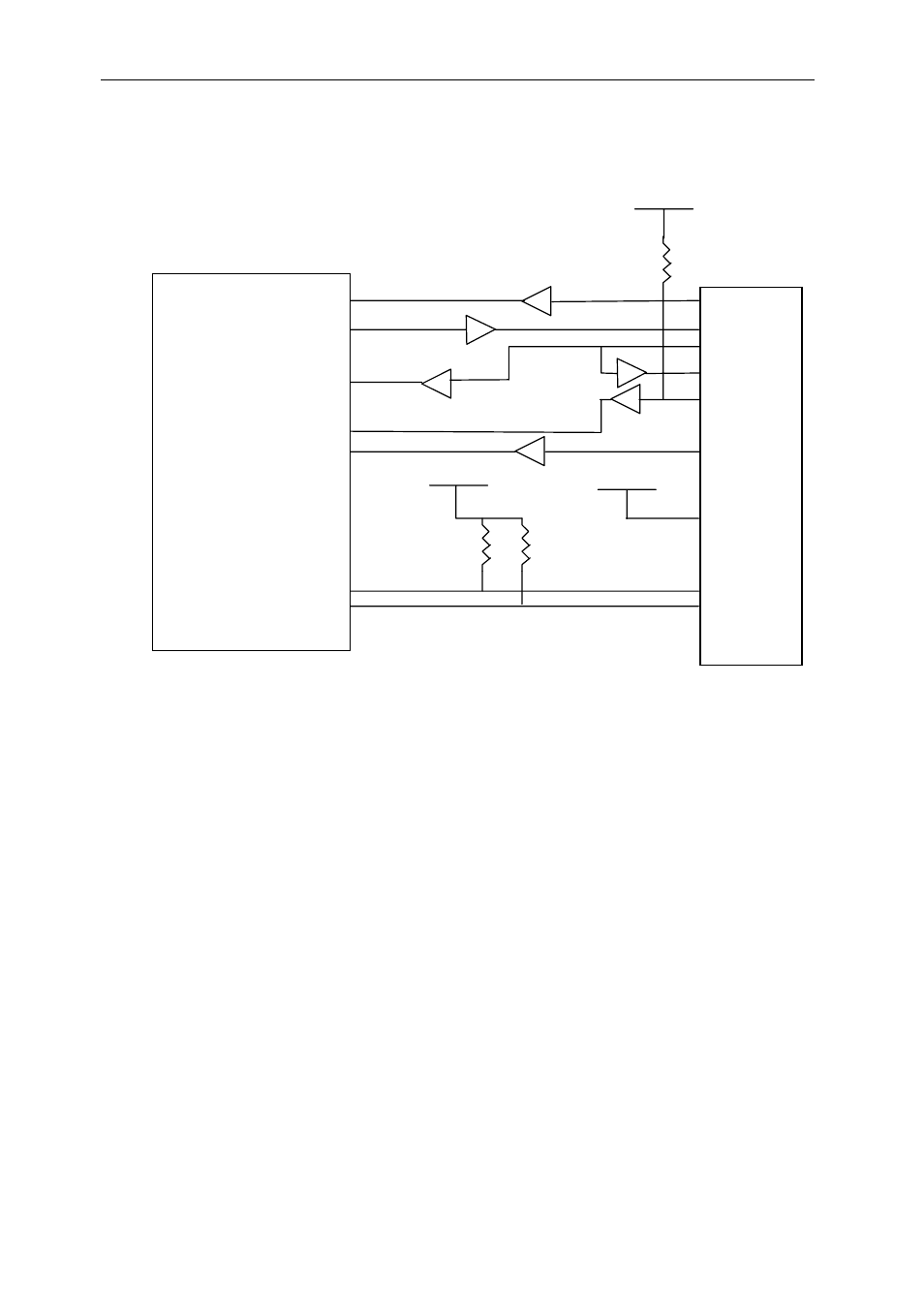
The JTAG circuit for a slave target board is shown in Figure 15. Using the
correct buffers and connectivity is essential to achieving a working JTAG
interface.
VCC
Figure 15: JTAG Slave circuit
All buffers are of type 74FCT244 (5V) / 74LV244 (3.3V) or equivalent.
N.B. When the JTAG device is NON-5v tolerant ensure that 3.3v buffers
are used.
4k7
4k7
4k7
TDI
TDO
TCLK
TCLK_RET
TMS
/TRST
/RESET
PD /DETECT
CONFIG
EMU0
EMU1
VCC
VCC
EMU0
EMU1
JTAG Device
/TRST
TMS
TCLK
TDO
............................
Slave Connector
This manual is related to the following products: