3 jtag cabling – Sundance SMT310Q User Manual
Page 40
Version 2.1
Page 40 of 55
SMT310Q User Manual
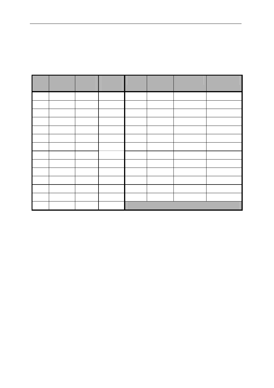
The following table shows connector pin-out and cable pair connections. This
is important, as the critical signals must be paired with a ground as shown.
The allocation to twisted pairs is based on grouping the data signals because
they change at the same time, so that crosstalk is not an issue. Each control
signal has its own ground:
Pin Twisted
Pair
RTI
Signal
RTO
Signal
Pin
Twisted
Pair
RTI Signal RTO Signal
1 1
I/O_OUT
I/O_IN
15 8
D2
D2
2 1 GND
GND 16 8
D3
D3
3 2 I/O_IN
I/O_OUT
17 9
D4
D4
4 2 GND
GND 18 9
D5
D5
5 3
/CSTRB
/CSTRB
19 10
D6
D6
6 3 GND
GND 20 10
D7
D7
7 4
/CRDY
/CRDY
21 11 VCC
VCC
8 4 GND
GND 22 11 GND GND
9 5
/CREQ
/CREQ
23 12
/RST_OUT
/RST_IN
10 5 GND
GND 24 12 GND
GND
11 6 /CACK
/CACK
25 13 /RST_IN
/RST_OUT
12 6 GND
GND 26 13 GND
GND
13 7 D0 D0
SHELL - SHIELD SHIELD
14 7 D1 D1
Table 13: Buffered Comport connector pinout
The overall shield is attached to the body of the metal plug shell.
The signal VCC is fused on the board at 1 amp; the fuse automatically resets
when the load is removed.
When the buffered comport is reset to input, pins 1 and 23 are always driven
and pins 3 and 25 are always receivers. When the buffered comport is reset to
output, pins 3 and 25 are always driven and pins 1 and 23 are always receivers.
12.3
JTAG cabling
The 20-way JTAG connectors require the following cabling components:
Cable plugs
3M Scotchflex 10120-6000EL, FES part 038739R
Plug shells
3M Scotchflex 10320-A200-00, FES part 038759A
Cable type
3M Scotchflex KUCKMPVVSB28-10PAIR, FES part 038780G