2 buffered external comport, 3 comport to pci interface, 1 comport registers (bar1, offset 1016) – Sundance SMT310Q User Manual
Page 16: Buffered external comport, Comport to pci interface, Comport registers (bar1, offset 10
Version 2.1
Page 16 of 55
SMT310Q User Manual
4.2
Buffered External Comport
The buffer consists of an FCT245AT type device with 64mA pull-down ability. All
signals are pulled up to +3.3 volts with 100-ohm resistors and the active devices
are mounted as closely as possible to the connector they serve. The back panel
connector is a 26 pin 3M type (3M part number 10226-5212JL).
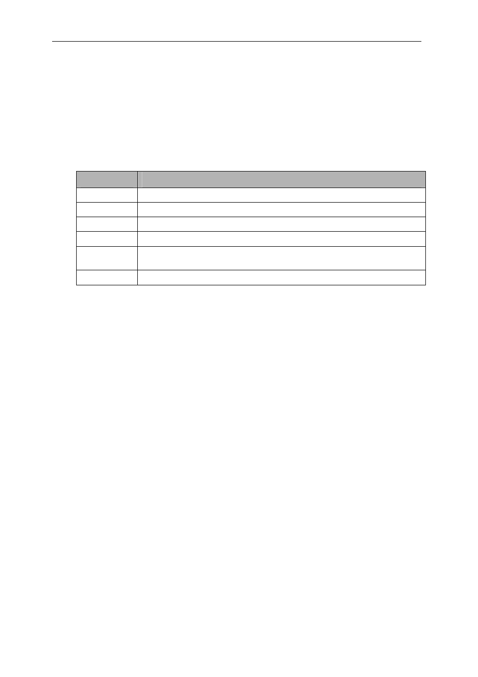
As well as ground signals and the 12 C4x comport signals, there are 6 additional
signals. These signals are NOT essential for communications:
Name
Description
I/O_OUT
Output high when port is outputting, output low when port is receiving.
I/O_IN
Input which prevents bus contention if connected to I/O_OUT
/RST_OUT
Active low open collector copy of the board reset drive.
/RST_IN
Active low board reset input, pulled up to 3.3V by 100 ohms.
VCC
1 AMP +5 Volt supply, with resetable 1 Amp fuse, to power a remote buffer, if
required.
SHIELD
Overall cable shield, connected to plug shells and chassis.
Table 2: Buffered Comport Additional Signals
You can synchronise resetting a number of boards by chaining them together
with /RST_OUT of one driving /RST_IN of the next.
The SMT502-Buffer is the recommended cable assembly for the buffered
comport and can be purchased separately.
4.3
Comport to PCI Interface
The comport interface is memory-mapped to the PCI bridge as illustrated in
Table 8. The comport uses the control and data registers to detect the state of
the input and output FIFOs. The following section describes the bit definitions
for these registers.
4.3.1 Comport Registers (BAR1, Offset 10
16
)
The host can be connected to TIM site 1 using comport 3 (T1C3). This port is
bi-directional and will automatically switch direction to meet a request from
either the host or the DSP. Both input and output registers are 32 bits wide.
Data can only be written to COMPORT_OUT when STATUS [OBF] is 0. When
a word is received from the DSP, it is stored in COMPORT_IN and STATUS
[IBF] is set to 1. Reading COMPORT_IN will clear STATUS [IBF] and allow
another word to be received from the DSP.