Basic wiring diagram, English-3, Im 3 – Delta Electronics AC Drive VFD-F Series User Manual
Page 3: Vfd-f
English-3
General Specification
Other Functions
AVR, 2 kinds of S-Curve, Over-Voltage, Over-Current Stall Prevention, Fault Records,
Reverse inhibition, DC Brake, Momentary Power Loss restart, Auto torque and slip
compensation, PID Control, Parameter Lock/Reset, Frequency Limits, Adjustable Carrier
Frequency, 4 sets of Fan & Pump Control,
Protection
Self-testing, Over Voltage, Over Current, Under Voltage, Overload, Overheating, External
Fault, Electronic thermal, Ground Fault, Phase-loss
Built-in Reactor
DC Reactor: 25~215HP
AC Reactor: 250~300HP
Built-in Brake Chopper
1~20HP
Cooling Methods
Forced Fan-cooled
Installation Location
Altitude 1,000 m or lower, keep from corrosive gasses, liquid and dust
Pollution Degree
2
Ambient Temperature
-10
o
C to 40
o
C Non-Condensing and not frozen
Storage/ Transportation
Temperature
-20
o
C to 60
o
C
Ambient Humidity
Below 90% RH (non-condensing)
E
n
vi
ro
me
n
ta
l
Condit
ions
Vibration 9.80665m/s
2
(1G) less than 20Hz, 5.88m/s
2
(0.6G) at 20 to 50Hz
Approvals
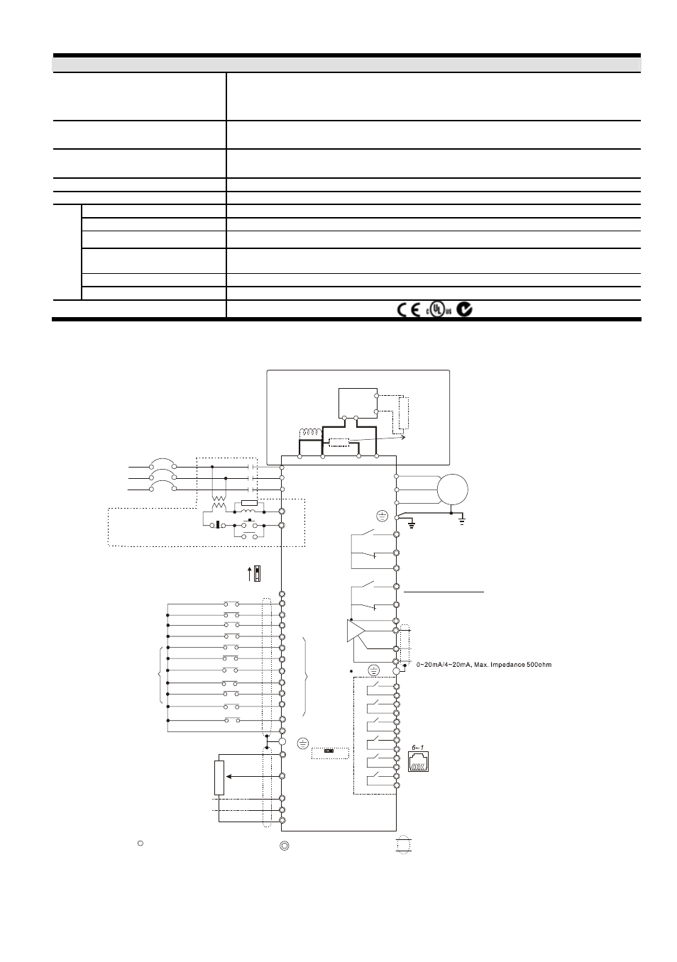
Basic Wiring Diagram
Users must connect wiring according to the following circuit diagram shown below.
NFB
R/L1
S/L2
T/L3
NFB
SA
OFF
ON
MC
RB1
RC1
U/T1
V/T2
W/T3
IM
3~
Motor
AFM2
RA1
RB1
RC1
Factory setting: output current
RS-485
Serial communication interface
Recommended Circuit
when power supply
is turned OFF by a
fault output
RA2
RB2
RC2
Sw2
0-10V
0-5V
AFM1
ACM
Factory setting: output frequency
0~10VDC/2mA
VFD-F
RA3
RC3
RA4
RC4
RA5
RC5
RA6
RC6
RA7
RC7
RA8
RC8
Relay B.D.
RY00
Analog Signal Common
Multi-function Analog
output terminal
Multi-function indication
output contacts
R/L1
S/L2
T/L3
FWD
REV
EF
MI1
MI2
MI3
MI4
MI6
MI5
DCM
+24V
FWD/STOP
REV/STOP
Digital Signal Common
AVI
ACI1
ACI2
ACM
Power supply
+10V 20mA
Master Frequency
0~10V/5V(47Kohm)
4~20mA
Analog Signal Common
+10V
5Kohm
3
2
1
*Don't apply the mains voltage
directly to above terminals.
MI7
MI8
4~20mA
(250ohm)
(250ohm)
E.F.
Multi-step1
Multi-step2
Multi-step3
Multi-step4
RESET
JOG
Accel/Decel prohibit
1/2 Accel/Decel switch
Factory
setting
Multi-
function
input
terminals
E
1: +EV 2: GND
5:NC
6: for communication
3: SG-
4: SG+
(Optional)
Main circuit (power) terminals
Control circuit terminals
Shielded leads & Cable
E
Sw1
Sink
Source
Factory Setting: SINK Mode
Please refer to following
wiring for SINK mode and
SOURCE mode.
+1
+2/B1
-
Jumper
DC Reactor
(Optional)
B2
BR
Brake
Resistor
(Optional)
P N
B1
B2
VFDB
Brake
Unit (Optional)
For 230V series, 1-15 hp models
460V series, 1-20hp models
Please refer to
Terminal Explanation
Please refer to following wiring
for other models
NOTE
:Do not plug a Modem or telephone line to the RS-485 communication port, permanent damage may
result. Pins 1 & 2 are the power sources for the optional copy keypad and should not be used while using RS-
485 communication.