Quick pt-link set-up, 2 connection and wiring information, Pt-link ii bacnet3 interface 6 – Orion System PT-Link II BACnet3 User Manual
Page 6: Zone, Figure 2: pt-link ii bacnet, Interface, Wiring, Enter clear esc prev next down up, Minus, Status setpoints schedules configuration alarms
Zone
Zone
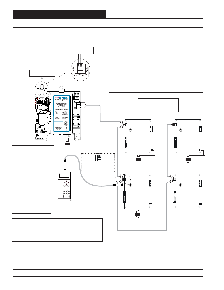
2. QUICK PT-LINK SET-UP
PT-Link II BACnet3 Interface
6
2.2 Connection and Wiring Information
Figure 2: PT-Link II BACnet
®
Interface
Wiring
Modular Service Tool
Mode
Selection
ENTER
CLEAR
ESC
PREV
NEXT
DOWN
UP
6
5
4
DEC
7
0
8
1
3
2
9
MINUS
-
STATUS
SETPOINTS
SCHEDULES
CONFIGURATION
ALARMS
ON
OVERRIDES
BALANCE - TEST
Line Voltage
PT-Link Interface
MS/TP Connection
To
Network
BACnet
®
MS/TP Connection
To
Network
BACnet
®
24 VAC
(10 VA)
Line Voltage
24 VAC
(8 VA)
Line Voltage
24 VAC
(8 VA)
Line Voltage
Controller
Controller
Controller
Controller
24 VAC
(8 VA)
Line Voltage
24 VAC
(8 VA)
SHLD
T
R
Typical Terminal Blocks. All
Wiring To Be T To T, SHLD
(G) To SHLD (G) & R To R
Note: All Programming Of
Controllers Must Be Done
Using The Modular Service
Tool. The Modular System
Manager Should Not Be
Used On A System That
Has A PT-Link Installed.
Caution: The BACnet
Communication Terminal Block
Must Be Disconnected Before
Connecting The Modular
Service Tool. After
Programming The
Controller(s), Disconnect The
Service Tool and Then
Reconnect The
Communication Terminal
Block.
®
Wiring Notes:
1.) All wiring to be in accordance with local and national electrical
codes and specifications.
2.) All communication wiring to be 18 gauge minimum, 2 conductor
twisted pair with shield. Use Belden #82760 or equivalent.
485
DRIVER
COMM
R
SH
T
LOOP
PROTO
LED1
LED2
TIMER
W_DOG
H-BEAT
POWER
MADE IN USA
Up To 4 Controllers
Can Be Interconnected.
Address Controllers
As Shown.
IMPORTANT WIRING NOTE:
Use the Daisy-Chain Topology As Shown in This Diagram.
DO NOT Use a Star Topology with Multiple Units Tied
Directly to the PT-Link II.
1
2
3
4
5
6
7
8
O
N
O
N
1
2
3
4
ON
RSGND
Address 1
Address 2
Address 3
Address 4