Edit menu, Limits, Name – Measurement Computing eZ-NDT version 6.0.9 User Manual
Page 37
eZ-NDT
878493
Windows and Menus 4-
17
Edit Menu
Limits . . .
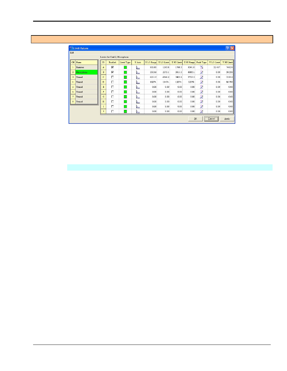
The Limit Values Window
The Limits Value window is used to configure the limit criteria for each input signal. You can define up to
10 limit ranges per response channel. Simply select the channel of interest; then define the range and limit
values. You can copy attributes of one range to another via the window’s Edit menu.
Limit Values
CH
The Channel number.
Name
This is the response channel for which you will be setting limits. Typically there is
only one Response Channel.
ID
For each significant peak you wish to monitor there should be a letter ID which has a
defined range and limits. IDs are lettered A through J.
Enabled
Check the box to enable an ID. Remove the checkmark to disable the ID.
Limit Type
Sets the limit as a “pass” limit or a “fail” limit. Typically green and red.
X Axis
Select the Spectral Graphic Image for Frequency (Hz) or
Select the smooth Sine Wave Graphic Image for Time-based (seconds).
Frequency is the most often used scale for the display’s X-axis.
X LO Range
X HI Range
Enter the lower and upper limit values of the frequency range.
eZ-NDT will find the maximum peak within this range.
X LO Limit
X HI Limit
Enter the upper and lower limits range.
For a green limit: if the frequency of the maximum spectral peak for the frequency
range is within the Limits range, the part passes.
For a red limit: if the frequency of the maximum spectral peak for the frequency
range is within the Limits range, the part fails.
Peak Type
Select the graphics image of peak rising or peak falling.
Y LO Limit
Y HI Limit
Enter the lower and upper limit values for the Amplitude.
For a green limit: if the amplitude of the maximum spectral peak for the frequency
range is within the amplitude range, the part passes.
For a red limit: if the amplitude of the maximum spectral peak for the frequency
range is within the amplitude range, the part fails.