Input channels tab – Measurement Computing eZ-NDT version 6.0.9 User Manual
Page 31
eZ-NDT
878493
Windows and Menus 4-
11
Preferences Panel
Investigation
Samples
Used to specify the number of samples to be used in the investigation mode. Up to
ten samples can be selected. On the main window, these will appear as numbers 1
through 10 in the Pass Fail columns.
File Size
(FIFO Records)
Enter the desired File Size. The required hard disk space for the requested file size is
displayed to the right of the data entry box and cannot exceed 2.1 gigabytes. Data is
stored to the history file after each NDT analysis.
Test Result
Flashes
The number of times the results of each test will flash on the screen.
Display HPF
(Hz)
Sets a frequency limit for the display window, such that all data at that frequency and
lower will be displayed as “0.” Thus, only data above the HPF value will be
displayed.
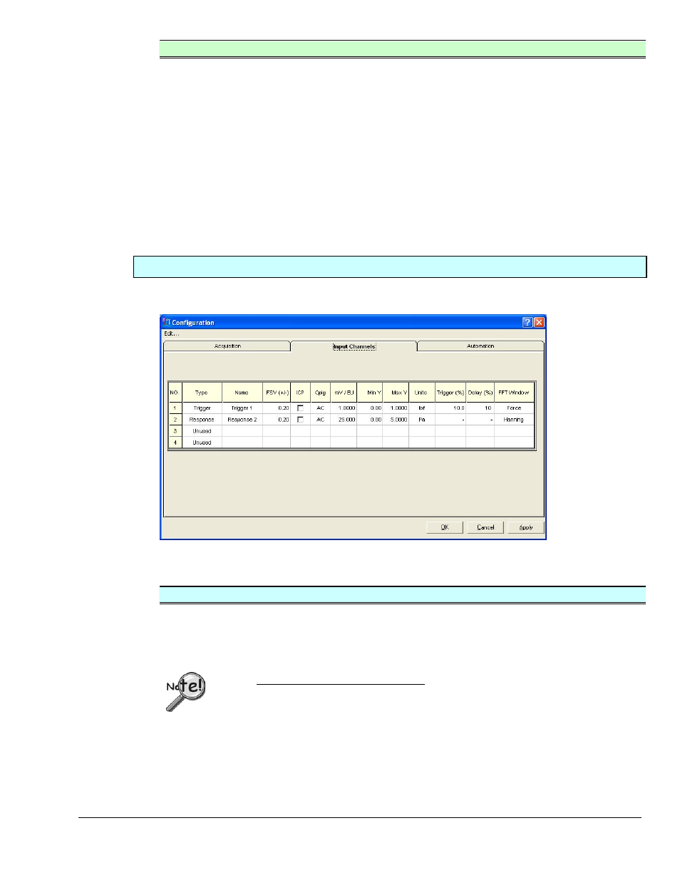
Input Channels Tab
The Input Channels Tab allows you to state the channel type (Trigger or Response), name the channel, and
set the channel parameters. Channel attributions can be copied and pasted to other channels.
The Configuration Window, “Input Channels” Tab
Input Channels Tab
No.
Used to select the channel to be configured.
Type
Select the instrument Type on the pull down menu. Types include Force, Response,
and Unused. You must have 1 Force Channel and 1 or more Response Channels.
[Default: Channel 1 is the Force channel; channel 2 is the Response channel;
channels 3 through 8 are unused.]
Users of ZonicBook-Medallion only: Configure the Dip Switches located under
the ZonicBook-Medallion Input Module for each probe. Typically, Hammers,
Microphones, and Accelerometers are Single Ended, AC Coupled, and ICP On.
Name
Enter a Name label for the channel; e.g., Trigger, Response, Microphone.
FSV (+/-)
Double-click on the cell and select the maximum Full Scale Voltage expected for the
instrument. Erroneous results will occur if you select a voltage value that is less than
the actual input voltage.
ICP
Used for ICP transducers. Checking “ICP” sources a bias current through the center
conductor of the input channel BNC connector.