Main i/o connector (j1), Signal definitions, 2 main i/o connector (j1) – Measurement Computing ADAC/5500 Series User Manual
Page 23
ADAC Series PCI Boards
795
- 18 -
ADAC/5500 Series User Manual
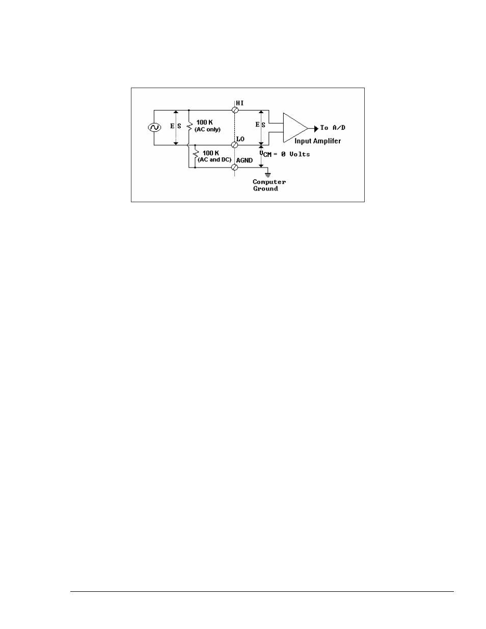
Figure 4.4 shows how to properly wire a Floating Source Signal in Fully-Differential configuration. In the
case where there is a combination of Ground Referenced Sources and Floating Sources, the Fully-Differential
mode should be used.
Figure 4.4
Fully-Differential Configuration for Floating Sources
4.2
MAIN I/O CONNECTOR (J1)
The main board connector is a 68 pin “SCSI III” style connector. This connector carries all the Analog I/O connections
as well as the 16 Digital I/O connections.
The ADAC/5500 input channels may be connected directly to any High Level voltage source. If long leads are run
from transducers to the system, it is very important that the leads be shielded to protect against pickup of power
frequency and other noise.
The factory has a line of screw terminal panels which can be used to ease field wiring to the PCI cards. Any of these
panels may be connected to the PCI card with an SCSC-III type cable (which can be ordered from the factory as a G55
cable).
The ADAC line of screw terminal panels includes:
ADAC-TB-8 - For use with the ADAC/5500MF boards only, this panel provides access to the 8 on-board analog input
channels, as well as the DIO ports 0 and 1 and various clocking and triggering signals.
ADAC-TB-16 - For use with the ADAC/5501MF, ADAC/5501MF-V, ADAC/5502MF, ADAC/5503HR,
ADAC/5503HR-V, and ADAC/5504HR boards only, this panel provides access to the 16 on-board analog input
channels, as well as the DIO ports 0 and 1, various clocking and triggering signals, and two optional DACs.
4.2.1 Signal
Definitions
The following is a description of each of the signals available at the J1-pin connector at the front edge of the board.
928