Step 3 – configure boards, Step 3 – configure boards warning – Measurement Computing ADAC/5500 Series User Manual
Page 14
ADAC Series PCI Boards
795
- 9 -
ADAC/5500 Series User Manual
7. Align the groove in the ADAC/5500 Series board’s PCI edge-connector with the ridge of the desired PCI
slot. See preceding right-hand figure.
8. Push the board firmly into the PCI slot. The board should “snap” into position.
9. Secure the board by inserting the rear-panel adapter-plate screw.
10. Using the previous steps, install additional boards into available PCI bus-slots, if applicable to your
application.
11. Replace the computer’s cover.
12. Plug in all cords and cables that were removed in step 1.
13. Apply power to, and start up the PC.
Note: At this point some PCs may prompt you to insert an installation disk. While this is rare, if you do
receive such a prompt simply place the install CD-ROM into the disk drive and follow additional
screen prompts.
STEP 3 – CONFIGURE BOARDS
WARNING
Always turn the computer power OFF and unplug it before connecting or disconnecting a
screw terminal panel or a cable to the PCI card. Failure to do so could result in electric
shock, or equipment damage.
Before you can use your ADAC/5500 Series Board, you will need to configure it according to information
contained in chapters 3 and 4 of this document. However, prior to doing so you may find it helpful to review
the following points:
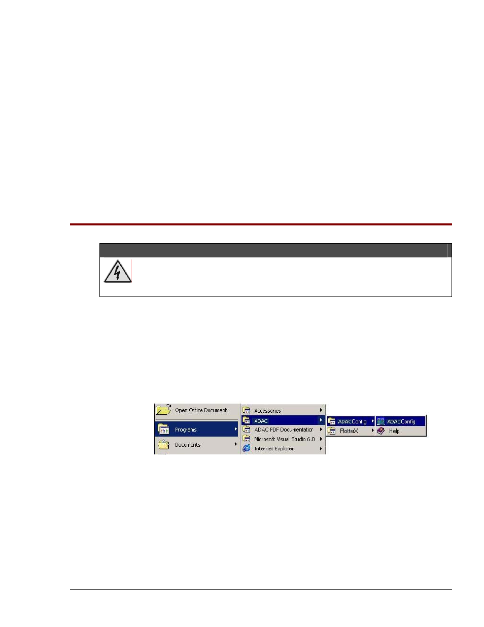
All configuration, including data-acquisition settings such as analog input, data collection rates,
input voltage range, and operating modes are made through ADAC configuration software. The
ADAC configuration software (ADAC Config) file can be accessed from the Windows desktop
Start Menu by navigating as follows:
Start
⇒ Programs ⇒ ADAC ⇒ ADACConfig ⇒ ADAC Config
Desktop Path to ADAC Config
•
ADAC ADLIB WDM software drivers provide an application level software interface to
Windows 98/ME/NT/2000/XP. Software packages such as LabVIEW
™ communicate through
our ADLIB driver software. These packages configure and collect, or output, acquisition data in a
GUI based interface.
•
• The ADAC/5501MF, ADAC/5502MF, ADAC/5503HR and ADAC/5504HR analog inputs are
impedance buffered and drive a differential gain amplifier that can be referenced in a number of
ways, allowing the following programmable input configurations: Single-Ended, Pseudo-
Differential, and Fully-Differential.
928