Dynamic bandwidth configuration, A.5 dynamic bandwidth configuration – Comtech EF Data turboIP-G2 User Manual
Page 169
turboIP-G2 Performance Enhancement Proxy
Revision 2
Appendix A
CD-TURBOIP-G2
A–5
A.5
Dynamic Bandwidth Configuration
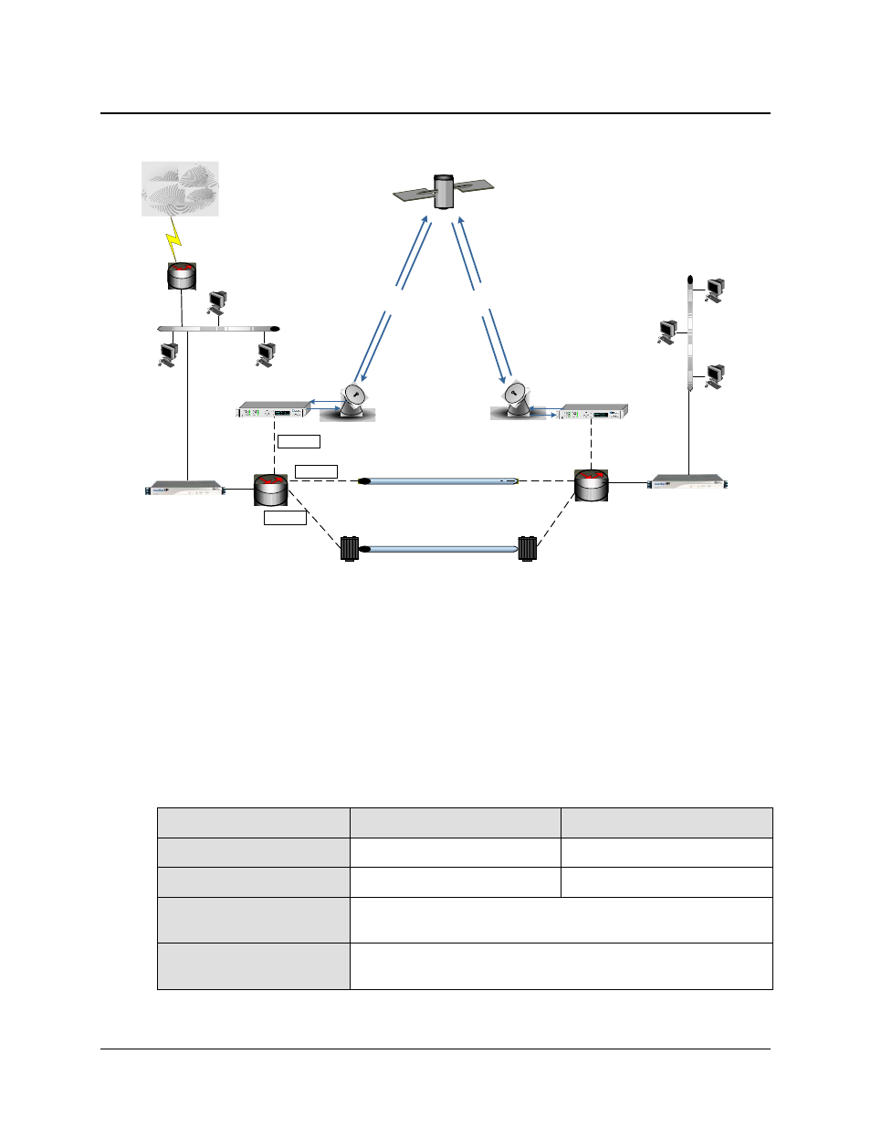
Figure A-4. Dynamic Bandwidth Configuration
For the Dynamic Bandwidth configuration example shown in Figure A-4, there are turboIP-G2s in
place in a simple Point-to-Point link, but there is more than a single path available between the Hub
and the Remote Sites. Path A is a fiber optic link, Path B is a terrestrial T1 link, and Path C is a 1
Mbps satellite link. Routers are used at both sites to dynamically select the best path available. The
turboIP-G2s are placed just before the router so that all traffic passes through the turboIP-G2s
regardless of the path used. In this dynamic bandwidth environment, the turboIP-G2s need to set to
Per-Connection Congestion Control to optimize the TCP acceleration for whichever path is used.
The following table defines the configuration settings for each turboIP-G2:
Configuration Parameter
Hub turboIP-G2
Remote turboIP-G2 (1 & 2)
WAN Transmission Rate
45 Mbps (set to the maximum rate)
45 Mbps (set to the maximum rate)
Congestion Control
Per-Connection Per-Connection
Selective Acceleration
No Selective Acceleration Rules are required. Rules could be added to
prioritize or set BW limits on any type of traffic.
Route Table
No Route Table entries are required. Routes could be added to allow remote
access from outside of LAN subnet.
1
M
b
p
s
1
Mb
p
s
Hub Site
1
M
b
p
s
1
M
b
p
s
Internet
WAN
LAN
Remote Site
WAN
LAN
Fiber Optic
Fiber optic transmitter
Fiber optic transmitter
T1 Terrestrial
Path C
Path B
Path A