Control port connections, Ps-8810, Connections control port – BSS Audio Prosys PS-8810 Owner's Manual User Manual
Page 41
- 41 -
PS-8810
DIGITAL SIGNAL PROCESSOR
Connections
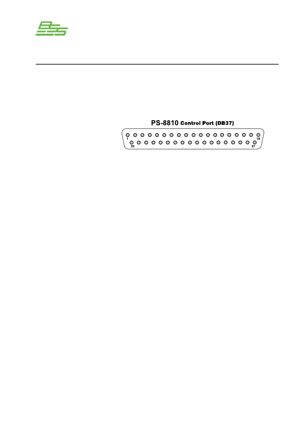
Control Port
Control Port
Connections
Connect any external circuits you plan to use to control and/or
monitor the BSS PS-8810 via the Control Port.
The diagram
below shows pin assignments for the Control Port. See the
Control Port (Section 16.0) for information on the operation of
the Control Port, and for examples of wiring circuits to the
Control Port connector.
PIN
PIN
PIN
PIN
1 D OUT 1
10 GND
19 D IN 8
28 GND
2 D OUT 2
11 GND
20 A OUT 9
29 +10V
3 D OUT 3
12 D IN 1
21 A OUT 10
30 A IN 1
4 D OUT 4
13 D IN 2
22 A OUT 11
31 A IN 2
5 D OUT 5
14 D IN 3
23 A OUT 12
32 A IN 3
6 D OUT 6
15 D IN 4
24 A OUT 13
33 A IN 4
7 D OUT 7
16 D IN 5
25 A OUT 14
34 A IN 5
8 D OUT 8
17 D IN 6
26 A OUT 15
35 A IN 6
9 +5V
18 D IN 7
27 A OUT 16
36 A IN 7
37 A IN 8
Control Port Pin Assignment
Pins 1 through 8 are assignable to manually select a binary (on/off)
value, chosen Preset status, or status of any logical binary control
or sensor (most likely gate and Preset).
Pins 20 through 27 provide an analogue output from 0 to +10VDC
that is assignable or can reflect an object (including faders) of the
unit.
A total of 1 amp of current is available from all outputs.
Pins 12 through 19 are assignable to logic Preset recall and general
control for logical type objects within the unit, and are assignable
to any combination of mute controls. Pins 30 through 37 function
as analogue inputs and are assignable to any combination of fader
controls.