Paxton Superchargers Ford 5.0L Mustang GT User Manual
Page 47
P/N: 4809664 v3.1, 06/12/2012
©2012 Paxton Automotive
All Rights Reserved, Intl. Corp. Secured
47
7. ChARGE AIR COOLER (CAC) SySTEM
INSTALLATION, cont'd
Fig. 7C-6: Ø3.5” x 120° Cast Aluminum Elbow
C.
Discharge Duct Installation, Cold Side (cont'd):
Install a Ø4" silicone coupler onto the open
h.
end of the MAF housing and secure with a
#64 worm gear clamp.
Install the small end of the stepped coupler/
i.
MAF assembly over the open end of the pre-
viously-installed multiple-bend discharge tube.
Orient the MAF so the electrical connector
points at an angle rearward and to the driver
side (near the bend in the lower radiator hose)
and secure with a #48 worm gear clamp. (See
Fig. 7C-5)
Reconnect the MAF electrical connector.
j.
Install the Ø3.5” x 2" long black silicone cou-
k.
pler onto the throttle body and secure with a
#56 worm gear clamp.
Locate the Ø3.5” x 120° cast aluminum elbow.
l.
Insert the longer leg into the throttle body cou-
pler, clock to point toward the driver side, and
secure with a #56 worm gear clamp. (See Fig.
7C-6)
Install a Ø3.5” x 3" long silicone coupler onto
m.
the open end of the Ø3.5” x 120° cast alumi-
num elbow and secure with a #56 worm gear
clamp.
Locate the Ø3.5”-Ø4.0” 90° cast reducer
n.
elbow and install it between the Ø3.5” x 120°
cast aluminum elbow and the MAF housing.
Secure it with a #56 worm gear clamp at the
elbow end and a #64 worm gear clamp at the
MAF end. (See Fig. 7C-7)
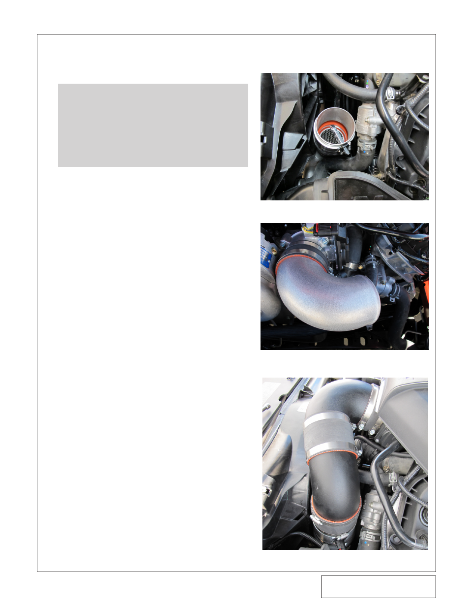
Fig. 7C-7: Cast Elbows, Final Position
NOTE: Take care to install the MAF in
the correct orientation relative to the air-
flow. When properly oriented, the air
should move from the resistor (FoMoCo
logo) end of the MAF module toward the
rounded end of the MAF module.
Fig. 7C-5: MAF Location (orientation will vary)