Paxton Superchargers Ford 5.0L Mustang GT User Manual
Page 46
P/N: 4809664 v3.1, 06/12/2012
©2012 Paxton Automotive
All Rights Reserved, Intl. Corp. Secured
46
7. ChARGE AIR COOLER (CAC) SySTEM
INSTALLATION, cont'd
Fig. 7C-1: Large Rubber Elbow
C.
Discharge Duct Installation, Cold Side:
Locate the remaining large 90° rubber elbow. Fit
a.
the shorter leg over the CAC outlet on the driver
side, pointing to the rear as much as possible,
and secure with a #52 worm gear clamp. (See
Fig. 7C-1)
Locate the remaining Ø3” x 90° aluminum tube
b.
with the tighter bend radius. Insert the shorter
leg into the open end of the large 90° rubber
elbow and orient it to point to the passenger side
of the car, with the open end passing just behind
the radiator as close as possible to the car’s
frame, and secure with a #52 worm gear clamp.
(See Fig. 7C-2)
Install a Ø3”x3" long black silicone straight cou-
c.
pler onto the open end of the Ø3” x 90° alumi-
num tube and secure with a #48 worm gear
clamp.
Locate the Ø3” aluminum tube with the multiple
d.
bends. Work the “S” bend portion up into the
engine compartment and insert the other end
(the end with the 90° bend) into the silicone cou-
pler in the previous step. Secure with a #48
worm gear clamp.
Locate the previously-removed OEM MAF wire
e.
module and install it into the included 3.8" MAF
housing using the included M4 fasteners, ensur-
ing the rubber seal is intact and properly seated.
(See Fig. 7C-3)
Locate the long stepped silicone coupler with the
f.
pre-installed honeycomb flow straightener. (See
Fig. 7C-4)
Insert the end of the MAF housing (nearest the
g.
visible resistor and "FoMoCo" logo in the MAF
module) into the large opening of the stepped
coupler and secure with a #64 worm gear clamp.
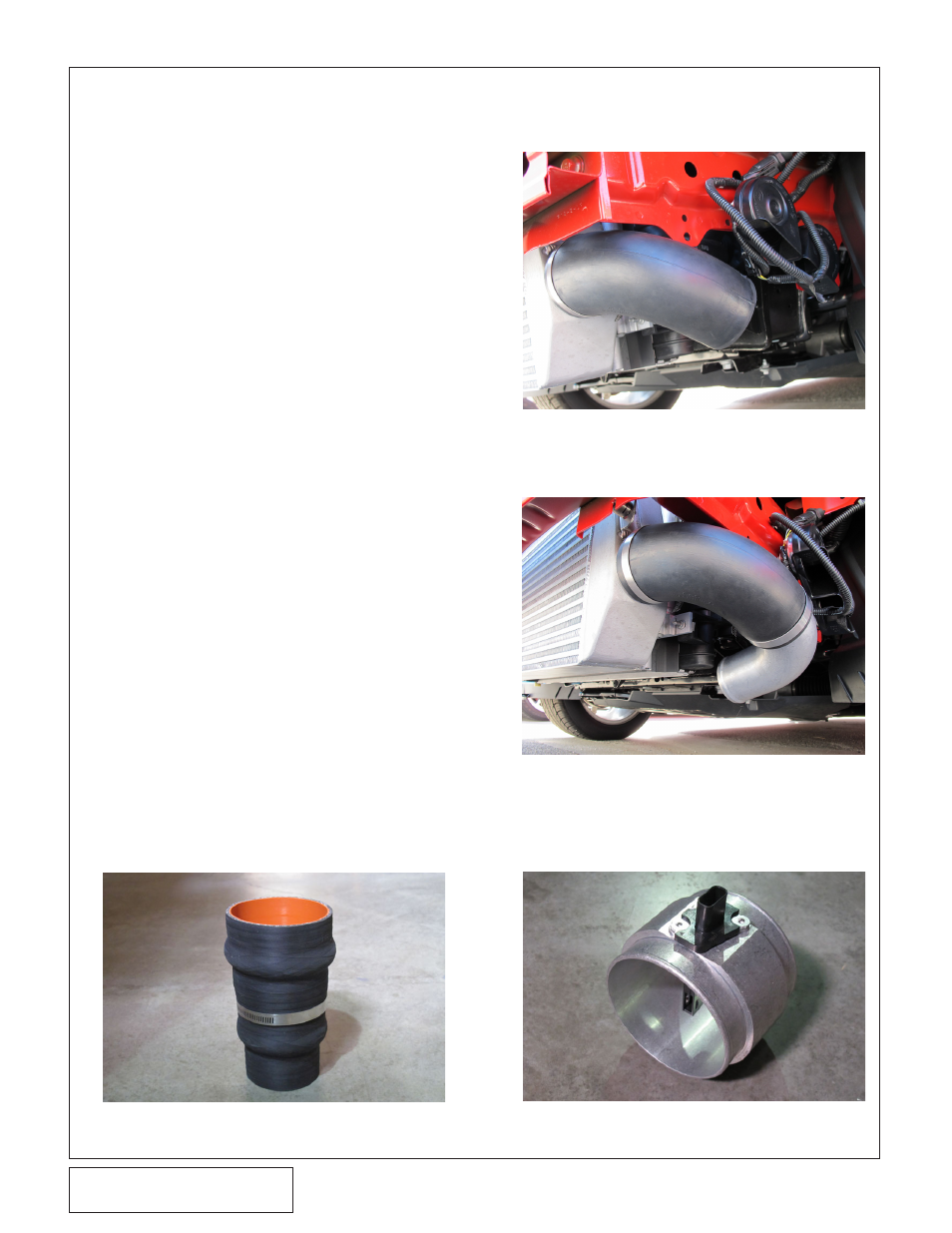
Fig. 7C-2: Tight 90° Tube
Fig. 7C-3: MAF Housing with OEM Insert
Fig. 7C-4: Stepped Coupler with Flow
Straightener