Gpio and audio pin-out schema, Gpio pin-out, Gpi pin-out information – Doremi ShowVault / IMB User Manual
Page 119: Gpo pin-out information, 16 gpio and audio pin-out schema, 1 gpio pin-out
____________________________________________________________________________________
SHV.OM.001293.DRM
Page 119 of 146
Version 1.5
Doremi Labs
16 GPIO and Audio Pin-Out Schema
This section provides information on the IMB revision E boards and their GPIO and
Audio pin-outs. To view a full list of technical specifications for the IMB, please see
document number CRT.OM.001118.DRM and contact Doremi Tech Support to receive
it.
16.1 GPIO Pin-Out
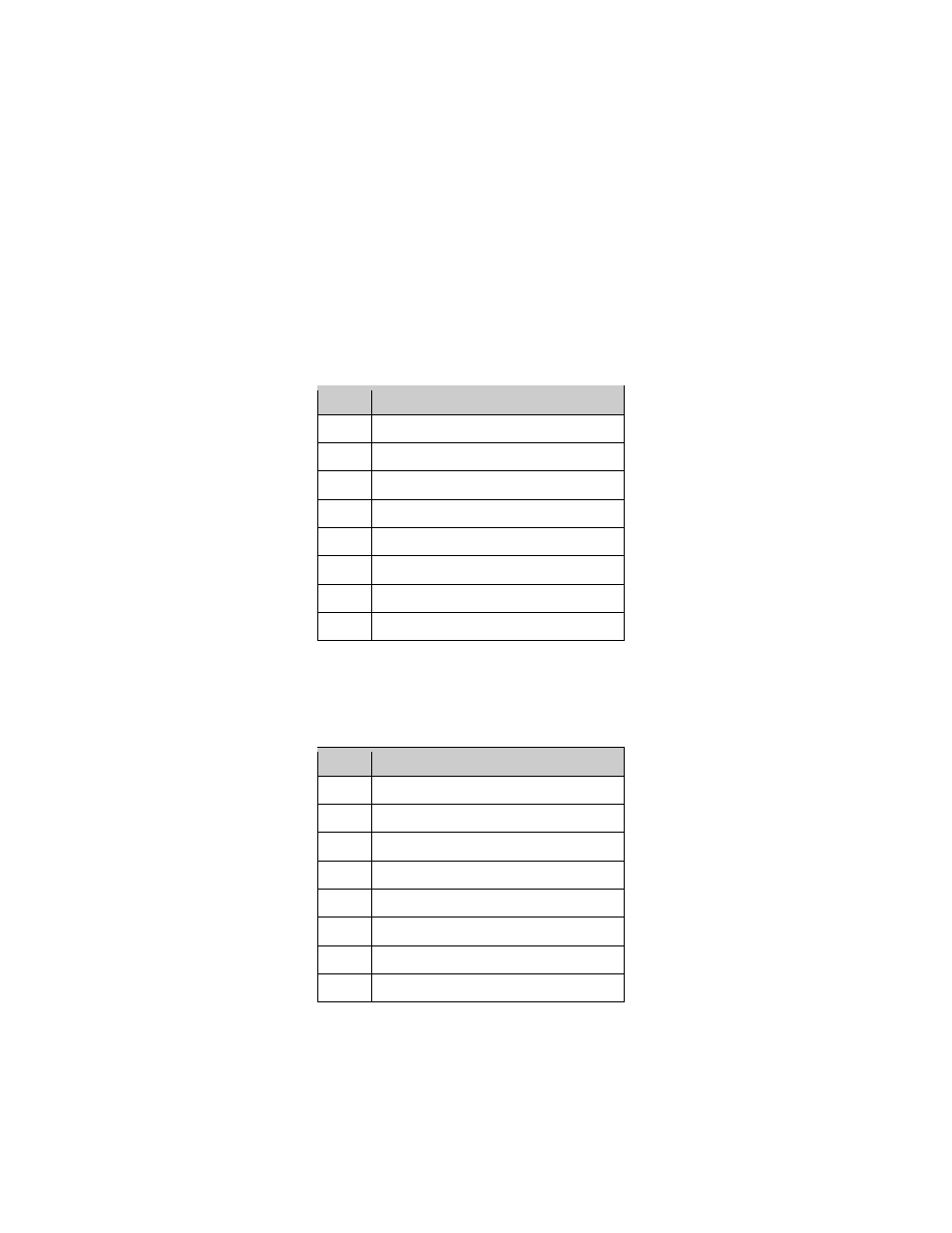
16.1.1 GPI Pin-Out Information
4 GPI on RJ45 Connectors (see Table below):
Pin #
Signal
1
GPI 0+
2
GPI 0-
3
GPI 1+
4
GPI 2+
5
GPI 2-
6
GPI 1-
7
GPI 3+
8
GPI 3-
16.1.2 GPO Pin-Out Information
8 GPO on RJ45 Connectors (see Table below):
Pin #
Signal
1
GPO 0
2
GPO 1
3
GPO 2
4
GPO 4
5
GPO 5
6
GPO 3
7
GPO 6
8
Ground