Interface operation, Altera daughter card (proto1) interface, 10/100 ethernet – Altera Cyclone II EP2C35 PCI Development Board User Manual
Page 24: Interface operation –14
2–14
Core Version 4.0.0
Altera Corporation
Cyclone II EP2C35 PCI Development Board Reference Manual
May 2005
Interface Operation
Interface
Operation
This section describes the board’s expansion and debugging interface
operation.
The board includes the following interfaces:
■
Altera daughter card (PROTO1)
■
10/100 Ethernet
■
RS-232 serial
■
AS interface
■
JTAG
■
SignalTap
®
II logic analyzer via the JTAG debug interface
■
Mictor probe
Altera Daughter Card (PROTO1) Interface
Board connectors J1, J6, and J7 allow the board to accept optional boards
with an Altera daughter card (PROTO1) interface. These connectors can
also be used for general purpose debugging, or an expansion interface
with 41 pins of LVTTL signals, which are shared with the Mictor probe
connector (J4).
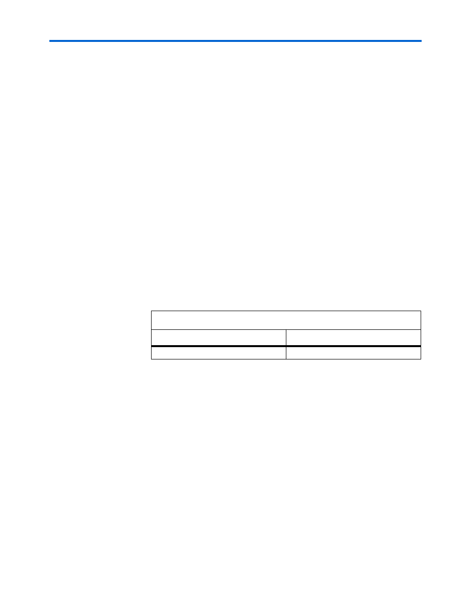
Table 2–16
shows the maximum allowed current draw for the Altera
daughter card (PROTO1) interface.
f
For more information about the following:
■
The Altera daughter card interface and to guarantee a longer life for
the card, refer to either the Stratix II or Cyclone II Editions of the Nios
Development Board Reference Manuals.
■
Available Altera daughter cards that can be used with the PCI
development board, Cyclone II edition, refer to
www.altera.com/devkits.
10/100 Ethernet
Board reference U3 is an SMSC LAN91C111 10/100 Ethernet MAC/PHY,
and board reference RJ1 is an RJ-45 connector with integrated magnetics
and activity LEDs.
Table 2–16. Maximum Allowed Current Draw for Altera Daughter Card
Voltage (V)
Maximum Current (A)
3.3
2A