Note (1) – Altera Cyclone II EP2C35 PCI Development Board User Manual
Page 13
Altera Corporation
Core Version 4.0.0
2–3
May 2005
Cyclone II EP2C35 PCI Development Board Reference Manual
Board Components & Interfaces
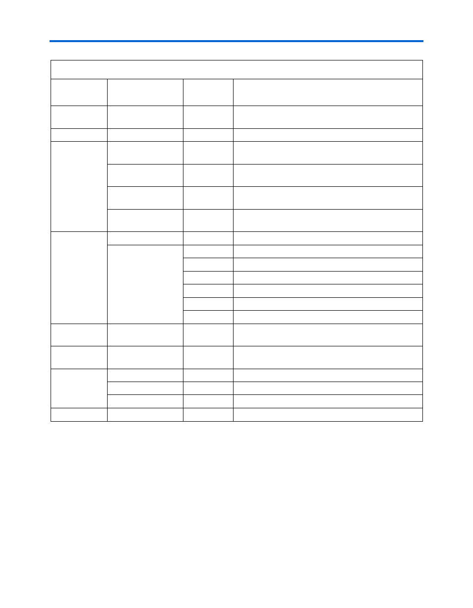
User indicator
User LEDs
D1 through
D8
User configurable.
Power
Power connector
J2
External power supply connector.
Power
indicators
+5.0-V power OK
LED
D15
5.0-V power supply indicator.
+3.3-V power OK
LED
D13
3.3-V power supply indicator.
+1.8-V power OK
LED
D14
1.8-V power supply indicator.
+1.2-V power OK
LED
D16
1.2-V power supply indicator.
Test points
VREF
TP4
VREF test point near VTT/VREF regulator.
Ground
TP1
Ground test point near power connector.
TP2
Ground test point near PWR SWITCH.
TP3
Ground test point near MICTOR.
TP5
Ground test point near oscillator socket.
TP6
Ground test point near DDR2 SDRAM.
TP7
Ground test point near QDRII SRAM.
Expansion
interface
Altera
®
daughter
card (PROTO1)
J1, J6, J7
Interface to Altera daughter card (PROTO1).
I/O
10/100 Ethernet
U3, RJ1,
OSC1
10/100 Ethernet MAC/PHY, RJ-45 connector,
25-MHz oscillator.
Serial I/O
RS-232
U12, J12
RS-232 serial interface level shifter, DB9 connector.
RS-232 Tx LED
D18
RS-232 transmitter active indicator.
RS-232 Rx LED
D17
RS-232 receiver active indicator.
Debug
Mictor probe
J4
Mictor probe interface for Agilent logic analyzers.
Note to
:
(1)
The Cyclone II EP2C35 PCI Development Board was designed to use either the EP2C35F672, EP2C50F672, or
EP2C70F672 device. However, the board ships with—and was only tested with—the EP2C35F672 device.
Table 2–1. Cyclone II EP2C35 PCI Development Board Components & Interfaces (Part 2 of 2)
Type
Component/
Interface
Board
Reference
Description