Transaction model of the sld infrastructure – Altera Virtual JTAG IP Core User Manual
Page 7
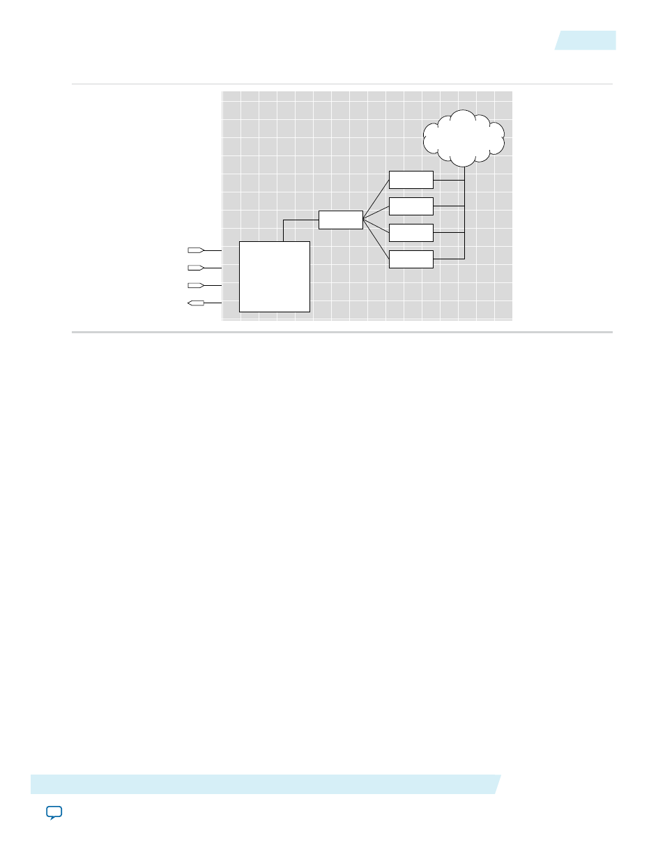
Figure 4: System Level Debugging Infrastructure Functional Model
JTAG Tap
Controller
TC
TM
TD
TD
FPGA
SLD Node
SLD Node
SLD Node
SLD Node
SLD Hub
User’s Design
(Core Logic)
Transaction Model of the SLD Infrastructure
In the presence of an application that requires the JTAG resource, the Quartus II software automatically
implements the SLD infrastructure to handle the arbitration of the JTAG resource. The communication
interface between JTAG and any IP cores is transparent to the designer. All components of the SLD
infrastructure, except for the JTAG TAP controller, are built using programmable logic resources.
The SLD infrastructure mimics the IR/DR paradigm defined by the JTAG protocol. Each application
implements an Instruction Register, and a set of Data Registers that operate similarly to the Instruction
Register and Data Registers in the JTAG standard. Note that the Instruction Register and the Data Register
banks implemented by each application are a subset of the
USER1
and
USER0
Data Register chains. The SLD
infrastructure consists of three subsystems: the JTAG TAP controller, the SLD hub, and the SLD nodes.
The SLD hub acts as the arbiter that routes the
TDI
pin connection between each SLD node, and is a state
machine that mirrors the JTAG TAP controller state machine.
The SLD nodes represent the communication channels for the end applications. Each instance of IP requiring
a JTAG communication resource, such as the SignalTap II Logic Analyzer, would have its own communication
channel in the form of a SLD node interface to the SLD hub. Each SLD node instance has its own Instruction
Register and bank of DR chains. Up to 255 SLD nodes can be instantiated, depending on resources available
in your device.
Together, the sld_hub and the SLD nodes form a virtual JTAG scan chain within the JTAG protocol. It is
virtual in the sense that both the Instruction Register and DR transactions for each SLD node instance are
encapsulated within a standard DR scan shift of the JTAG protocol.
The Instruction Register and Data Registers for the SLD nodes are a subset of the
USER1
and
USER0
Data
Registers. Because the SLD Node IR/DR register set is not directly part of the IR/DR register set of the JTAG
protocol, the SLD node Instruction Register and Data Register chains are known as Virtual IR (VIR) and
Virtual DR (VDR) chains. The figure below shows the transaction model of the SLD infrastructure.
Altera Corporation
Virtual JTAG Megafunction (sld_virtual_jtag)
7
Transaction Model of the SLD Infrastructure
UG-SLDVRTL
2014.03.19