The sld hub decodes, N) • an assertion of the, Signal, if available on the device – Altera Virtual JTAG IP Core User Manual
Page 21
HUB_FORCE_IR
capture must be issued whenever you capture the VIR from a target SLD node that is different
than the current active node. DR Scan Shift 1 targets the SLD hub VIR to force a captured value from Virtual
JTAG instance 1 and is shown as the VIR_CAPTURE command. DR Scan Shift 2 targets the VIR of Virtual
JTAG instance.
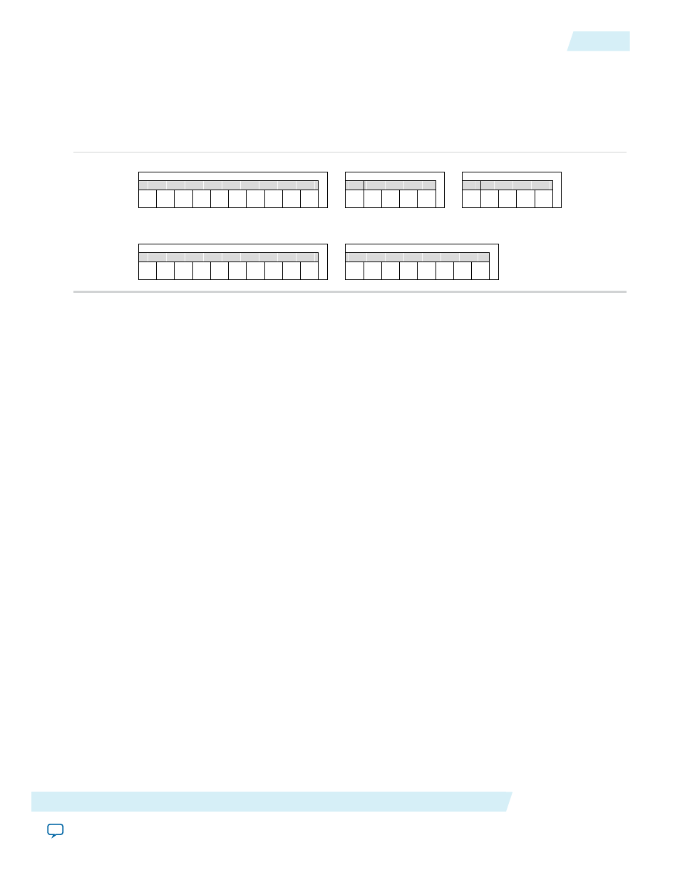
Figure 11: Equivalent Bit Pattern Shifted into Device by VIR/VDR Shift Commands with Captured IR Values
Virtual IR Scan
Virtual DR Scan
IR Scan Shift
IR Scan Shift
DR Scan Shift 1
DR Scan Shift
USER1
USER0
VIR Value
VDR Value
Addr
0
0
0
0
0
0
1
0
1
0
0
0
0
0
0
0
0
0
0
0
0
0
1
1
1
1
0
0
1
1
0
1
0
DR Scan Shift 2
VIR Value
Addr
0
0
0
1
1
If you use an embedded processor as a controller for the JTAG chain and your Virtual JTAG
megafunction instances, consider using the JAM Standard Test and Programming Language (STAPL).
Note:
JAM STAPL is an industry-standard flow-control-based language that supports JTAG communication
transactions. JAM STAPL is open source, with software downloads and source code available from
the Altera website.
Related Information
•
•
Reset Considerations when Using a Custom JTAG Controller
The SLD hub decodes
TMS
independently to determine the JTAG controller state. Under normal operation,
the SLD hub mirrors all of the JTAG TAP controller states accurately. The JTAG pins (
TCK
,
TMS
,
TDI
, and
TDO
) are accessible to the core programmable logic; however, the JTAG TAP controller outputs are not visible
to the core programmable logic. In addition, the hard JTAG TAP controller does not use any reset signals
as inputs from the core programmable logic.
This can cause the following two situations in which control states of the SLD hub and the JTAG TAP
controller are not in lock-step:
• An assertion of the device wide global reset signal (
DEV_CLR
n)
• An assertion of the
TRST
signal, if available on the device
DEV_CLR
n resets the SLD hub but does not reset the hard TAP controller block. The TAP controller is meant
to be decoupled from
USER
mode device operation to run boundary scan operations. Asserting the global
reset signal does not disrupt boundary-scan test (BST) operation.
Conversely, the
TRST
signal, if available, resets the JTAG TAP controller but does not reset the SLD hub.
The
TRST
signal does not route into the core programmable logic of the PLD.
To guarantee that the states of the JTAG TAP controller and the SLD hub state machine are properly
synchronized,
TMS
should be held high for at least five clock cycles after any intentional reset of either the
Altera Corporation
Virtual JTAG Megafunction (sld_virtual_jtag)
21
Reset Considerations when Using a Custom JTAG Controller
UG-SLDVRTL
2014.03.19