Issuing the hub_info instruction – Altera Virtual JTAG IP Core User Manual
Page 30
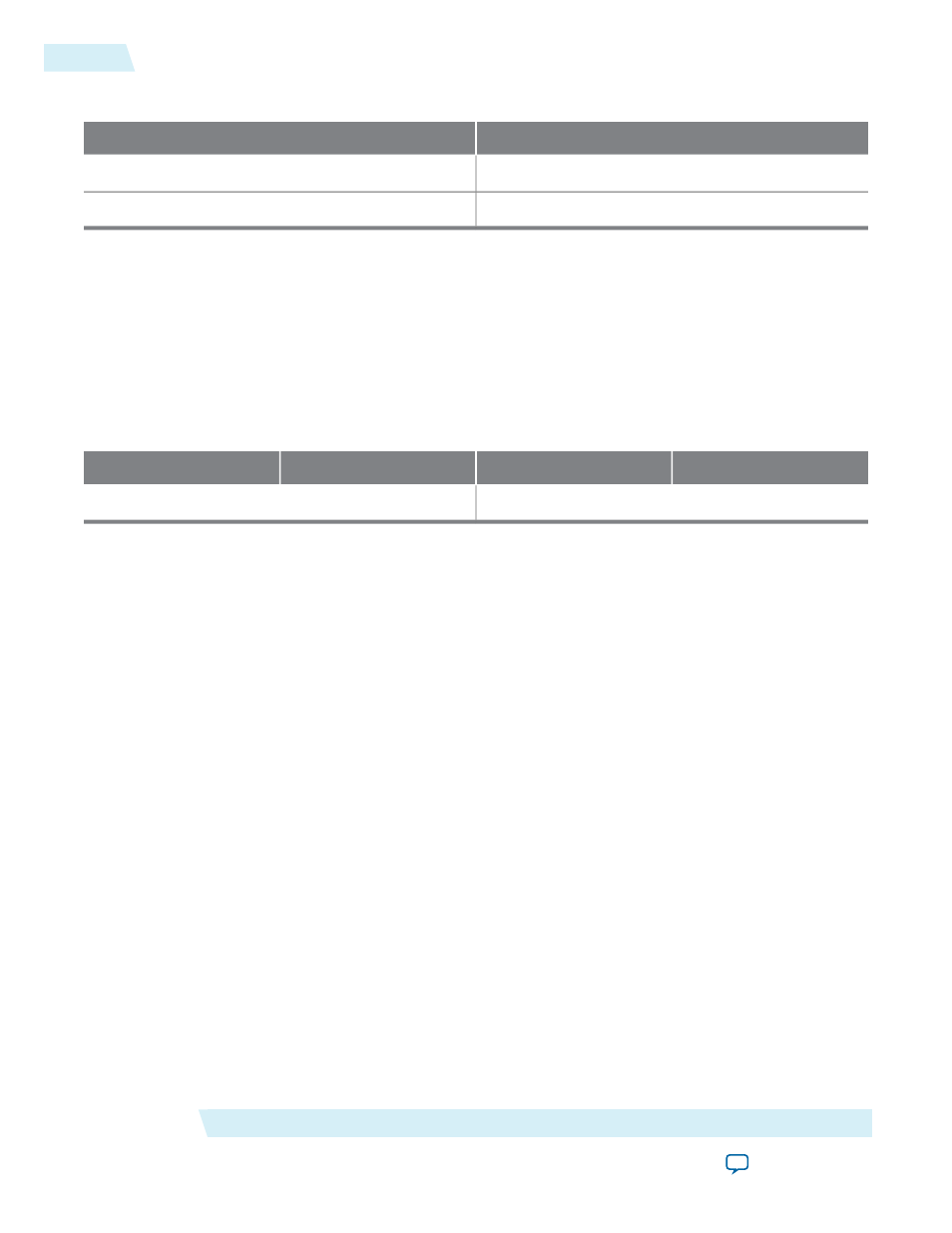
Table 10: USER1 and USER2 Instruction Values
Binary Pattern
Instruction
00 0000 1100
USER0
00 0000 1110
USER1
The
USER1
instruction targets the virtual IR of either the
sld_hub
or a
SLD
node. That is, when the
USER1
instruction is issued to the device, the subsequent DR scans target a specific virtual IR chain based on an
address field contained within the DR scan. The table below shows how the virtual IR, the DR target of the
USER1
instruction is interpreted.
The
VIR_VALUE
in the table below is the virtual IR value for the target
SLD
node. The width of this field is m
bits in length, where m is the length of the largest VIR for all of the
SLD
nodes in the design. All
SLD
nodes
with VIR lengths of fewer than m bits must pad
VIR_VALUE
with zeros up to a length of m.
Table 11: USER1 DR
0
m – 1
m
m + n – 1
VIR_VALUE
[(m – 1)..0]
ADDR
[(n – 1)..0]
The
ADDR
bits act as address values to signal the active
SLD
node that the virtual IR shift targets.
ADDR
is n
bits in length, where n bits must be long enough to encode all
SLD
nodes within the design, as shown below.
n = CEIL(log
2
(Number of SLD_nodes +1))
The SLD hub is always
0
in the address map, as shown below.
ADDR[(n -1)..0] = 0
Discovery and enumeration of the SLD instances within a design requires interrogation of the
sld_hub
to
determine the dimensions of the
USER1
DR (m and n) and associating each SLD instance, specifically the
Virtual JTAG megafunction instances, with an address value contained within the
ADDR
bits of the
USER1
DR.
The discovery and enumeration process consists of the following steps:
1. Interrogate the SLD hub with the
HUB_INFO
instruction.
2. Shift out the 32-bit HUB IP Configuration Register to determine the number of SLD nodes in the design
and the dimensions of the
USER1
DR.
3. Associate the Virtual JTAG instance index to an
ADDR
value by shifting out the 32-bit SLD node info
register for each SLD node in the design.
Issuing the HUB_INFO Instruction
The SLD hub contains the HUB IP Configuration Register and
SLD_NODE_INFO
register for each SLD node
in the design. The HUB IP configuration register provides information needed to determine the dimensions
of the
USER1
DR chain.
Virtual JTAG Megafunction (sld_virtual_jtag)
Altera Corporation
UG-SLDVRTL
Issuing the HUB_INFO Instruction
30
2014.03.19