Fir ii ip core signals, Fir ii ip core signals -8 – Altera FIR Compiler II MegaCore Function User Manual
Page 41
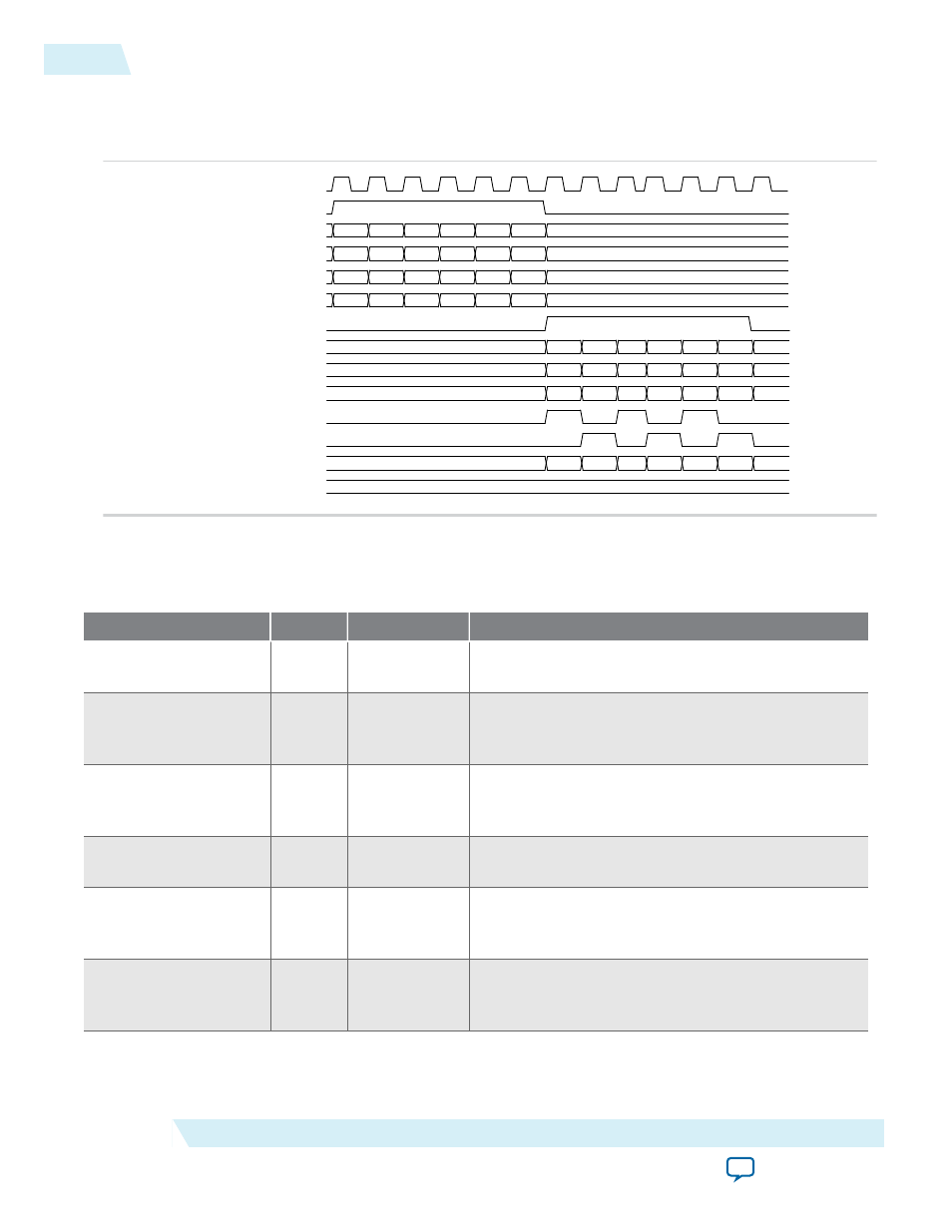
Figure 4-7: Timing Diagram of Multiple Channels on Multiple Wires
The FIR II IP core to the source interface when transferring a packet of data over multiple channels on
multiple wires.
clk
xOut_v
xOut_c[7:0]
xOut_0[7:0]
xOut_1[7:0]
xOut_2[7:0]
ast_source_valid
ast_source_data[7:0]
ast_source_data[15:8]
ast_source_data[23:16]
ast_source_sop
ast_source_eop
ast_source_channel
ast_source_error
A0
B0
A1
B1
A2
B2
C0
D0
C1
D1
C2
D2
E0
F0
E1
F1
E2
F2
0
1
0
1
0
1
A0
B0
A1
B1
A2
B2
C0
D0
C1
D1
C2
D2
E0
F0
E1
F1
E2
F2
0
1
0
1
0
1
X
X
X
X
00
FIR II IP Core Signals
Table 4-1: FIR II IP Core Signals with Avalon-ST Interface
Signal
Direction
Width
Description
clk
Input
1
Clock signal for all internal FIR II IP core filter
registers.
reset_n
Input
1
Asynchronous active low reset signal. Resets the FIR
II IP core filter control circuit on the rising edge of
clk
.
coeff_in_clk
Input
1
Clock signal for the coefficient reloading mechanism.
This clock can have a lower rate than the system
clock.
coeff_in_areset
Input
1
Asynchronous active high reset signal for the
coefficient reloading mechanism.
ast_sink_ready
Output
1
FIR filter asserts this signal when can accept data in
the current clock cycle. This signal is not available
when backpressure is turned off.
ast_sink_valid
Input
1
Assert this signal when the input data is valid. When
ast_sink_valid
is not asserted, the FIR processing
stops until you re-assert the
ast_sink_valid
signal.
4-8
FIR II IP Core Signals
UG-01072
2014.12.15
Altera Corporation
FIR II IP Core Functional Description