1 pulse output signals out and dir, Pulse output signals out and dir – ADLINK PCI-8154 User Manual
Page 30
20
Signal Connections
3.1
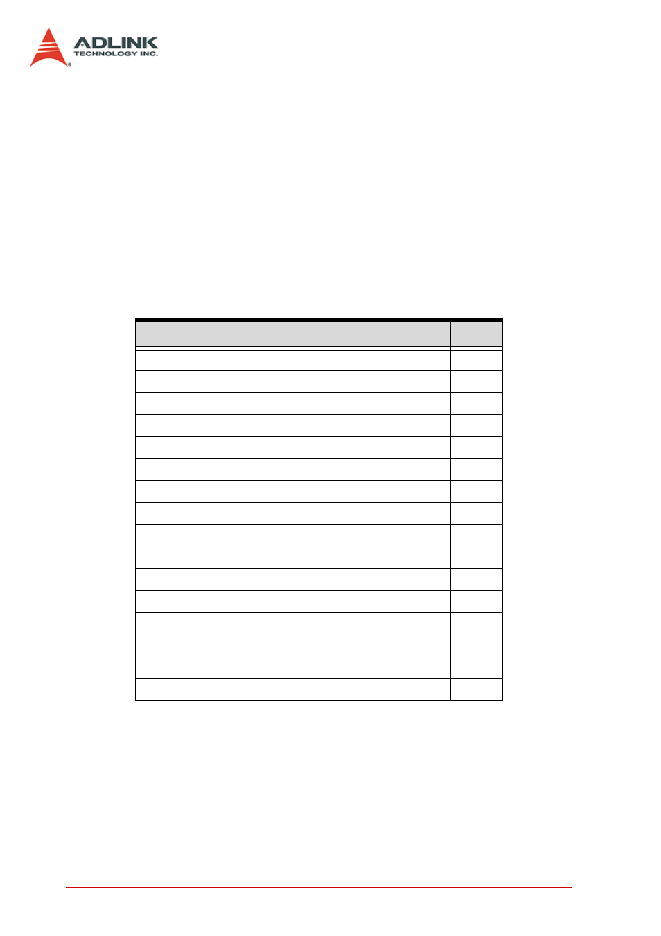
Pulse Output Signals OUT and DIR
There are 4 axes pulse output signals on the PCI-8154. For each
axis, two pairs of OUT and DIR differential signals are used to
transmit the pulse train and indicate the direction. The OUT and
DIR signals can also be programmed as CW and CCW signal
pairs. Refer to section 4.1.1 for details of the logical characteristics
of the OUT and DIR signals. In this section, the electrical charac-
teristics of the OUT and DIR signals are detailed. Each signal con-
sists of a pair of differential signals. For example, OUT0 consists
of OUT0+ and OUT0- signals. The following table shows all pulse
output signals on CN3.
The output of the OUT or DIR signals can be configured by jump-
ers as either differential line drivers or open collector output. Users
CN3 Pin No. Signal Name
Description
Axis #
3
OUT0+
Pulse signals (+)
0
4
OUT0-
Pulse signals (-)
0
5
DIR0+
Direction signal (+)
0
6
DIR0-
Direction signal (-)
0
21
OUT1+
Pulse signals (+)
1
22
OUT1-
Pulse signals (-)
1
23
DIR1+
Direction signal (+)
1
24
DIR1-
Direction signal (-)
1
53
OUT2+
Pulse signals (+)
2
54
OUT2-
Pulse signals (-)
2
55
DIR2+
Direction signal (+)
2
56
DIR2-
Direction signal (-)
2
71
OUT3+
Pulse signals (+)
3
72
OUT3-
Pulse signals (-)
3
73
DIR3+
Direction signal (+)
3
74
DIR3-
Direction signal (-)
3