4 software driver installation, 5 cn3 pin assignments: main connector, Software driver installation – ADLINK PCI-8154 User Manual
Page 23: Cn3 pin assignments: main connector, Table 2-1: cn3 pin assignments: main connector, Installation 13, No. name i/o function no. name i/o function
Installation
13
2.4
Software Driver Installation
1. Autorun the ADLINK All-In-One CD. Choose Driver
Installation -> Motion Control -> PCI-8154.
2. Follow the procedures of the installer.
3. After setup installation is completed, restart windows.
Note:
Please download the latest software from ADLINK website if
necessary.
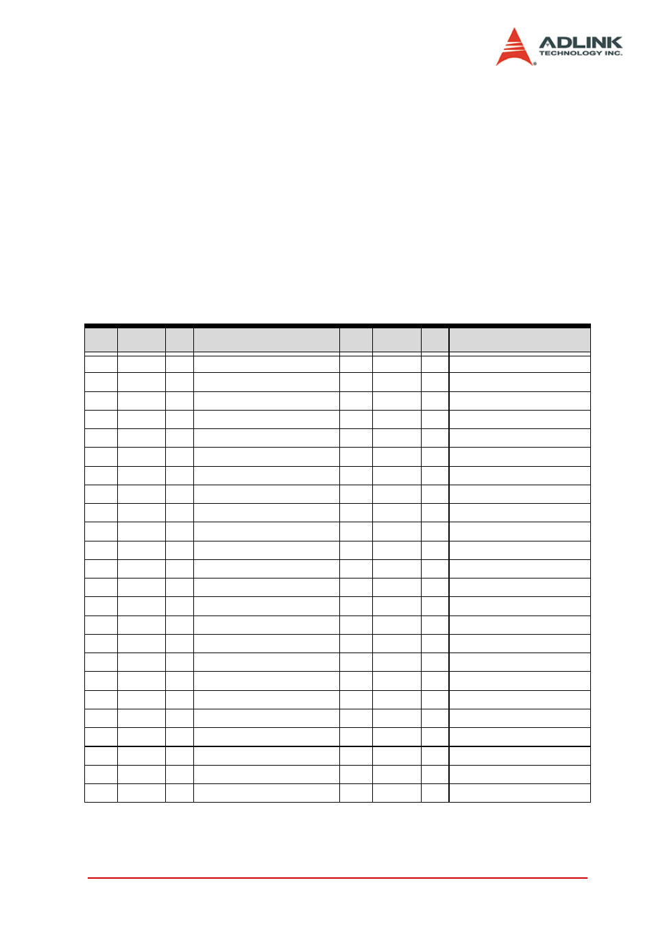
2.5
CN3 Pin Assignments: Main Connector
CN3 is the main connector for the motion control I/O signals.
No. Name I/O
Function
No. Name I/O
Function
1
VDD
O
+5V power supply output
51
VDD
O
+5V power supply output
2
EXGND
-
Ext. power ground
52
EXGND
-
Ext. power ground
3
OUT0+
O
Pulse signal (+)
53
OUT2+
O
Pulse signal (+)
4
OUT0-
O
Pulse signal (-)
54
OUT2-
O
Pulse signal (-)
5
DIR0+
O
Dir. signal (+)
55
DIR2+
O
Dir. signal (+)
6
DIR0-
O
Dir. signal (-)
56
DIR2-
O
Dir. signal (-)
7
SVON0
O
Servo On/Off
57
SVON2
O
Servo On/Off
8
ERC0
O
Dev. ctr, clr. Signal
58
ERC2
O
Dev. ctr, clr. signal
9
ALM0
I
Alarm signal
59
ALM2
I
Alarm signal
10
INP0
I
In-position signal
60
INP2
I
In-position signal
11
RDY0
I
Multi-purpose Input signal
61
RDY2
I
Multi-purpose Input signal
12
EXGND
Ext. power ground
62
EXGND
Ext. power ground
13
EA0+
I
Encoder A-phase (+)
63
EA2+
I
Encoder A-phase (+)
14
EA0-
I
Encoder A-phase (-)
64
EA2-
I
Encoder A-phase (-)
15
EB0+
I
Encoder B-phase (+)
65
EB2+
I
Encoder B-phase (+)
16
EB0-
I
Encoder B-phase (-)
66
EB2-
I
Encoder B-phase (-)
17
EZ0+
I
Encoder Z-phase (+)
67
EZ2+
I
Encoder Z-phase (+)
18
EZ0-
I
Encoder Z-phase (-)
68
EZ2-
I
Encoder Z-phase (-)
19
VDD
O
+5V power supply output
69
VDD
O
+5V power supply output
20
EXGND
-
Ext. power ground
70
EXGND
-
Ext. power ground
21
OUT1+
O
Pulse signal (+)
71
OUT3+
O
Pulse signal (+)
22
OUT1-
O
Pulse signal (-)
72
OUT3-
O
Pulse signal (-)
23
DIR1+
O
Dir. signal (+)
73
DIR3+
O
Dir. signal (+)
24
DIR1-
O
Dir. signal (-)
74
DIR3-
O
Dir. signal (-)
Table 2-1: CN3 Pin Assignments: Main Connector