Direct venting, Venting – A.O. Smith 960 through 967 User Manual
Page 5
Attention! The text in this document has been recognized automatically. To view the original document, you can use the "Original mode".
BTH S E R V I C E H A N D B O O K
N S T A L L A T I O N
VENTING
Equivalent Feet of Pipe Intake or Exhaust
VENT LENGTH TABLE
NUMBER OF 90°
ELBOWS
3” MINIMUM
PIPE (FEET)
3” MAXIMUM
PIPE (FEET)
4” MAXIMUM
PIPE (FEET)
ONE (1)
7
45
115
TWO (2)
7
40
110
THREE (3)
7
35
105
FOUR (4)
7
30
100
FIVE (5)
7
-
95
SIX (6)
7
-
90
4-inch PVC may be used for a MAXIMUM intake of ONE HUNDRED TWENTY (120) EQUIVALENT
FEET and a MAXIMUM exhaust of ONE HUNDRED TWENTY (120) EQUIVALENT FEET The
maximum number of 90° elbows with the 4-inch venting is six (6) on the intake and six (6) on the
exhaust. A 90° elbow is equal to five (5) equivalent feet of pipe. One (1) 90° elbow is equal to two
(2) 45° elbows. Any venting configuration using less than 50 equivalent feet should use 3-inch vent
ing. See Vent Length Table.
The 3-inch venting terminals (provided) must be used with the 4-inch venting by adding 4x3
reducing coupling at the venting terminals. A reducing coupling is also needed immediately after
the condensate elbow (exhaust) and immediately before the 3-inch blower adapter (intake) if direct
venting is installed. See Vent Length Table.
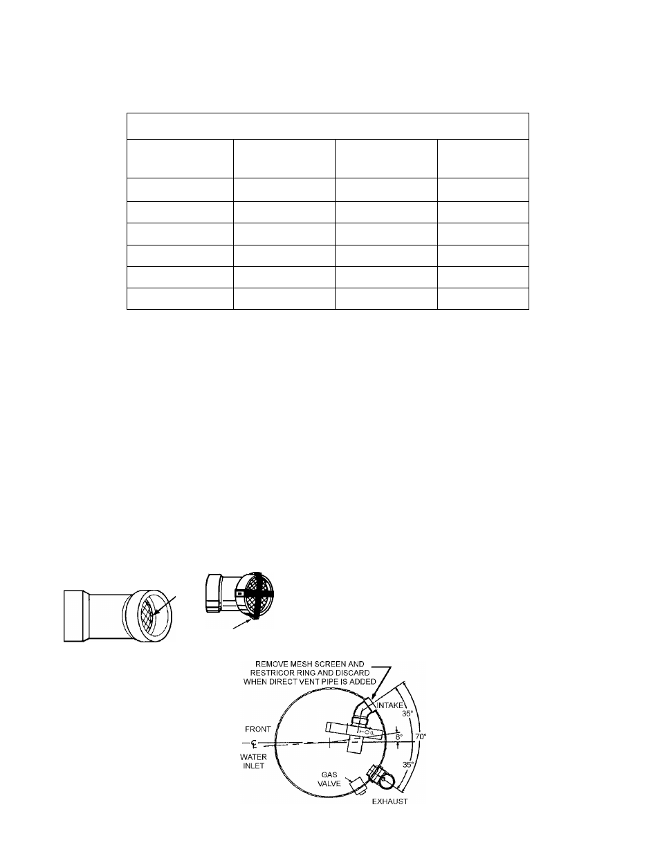
DIRECT VENTING
The air intake provided on the unit contains a mesh screen (see Figure below) to prevent large par
ticles from entering the unit.
3” (7.6CM) 45° PVC ELBOW WITH MESH SCREEN
MESH
SCREEN
RESTRICTOR
WARNING WHEN THE UNIT IS TO
BE SETUP AS A DIRECT VENT, THE
MESH SCREEN MUST BE REMOVED.
THE INLET VENT PIPE MAY THEN BE
GLUED TO THE AIR INTAKE (see follow
ing Figure) PROVIDED ON THE UNIT.
Technical Training Department
TC-044 Revision 6
A. O. Smith Water Products Co.
Ashland City, Tennessee © 2004