Pressure switch layout pressure switch wiring, Pressure swtches, Blower – A.O. Smith 960 through 967 User Manual
Page 36: Gas valve, Low gas pressure switch
Attention! The text in this document has been recognized automatically. To view the original document, you can use the "Original mode".
BTH S E R V I C E H A N D B O O K
C O M P O N E N T
N F O R M A T I O N
PRESSURE SWTCHES
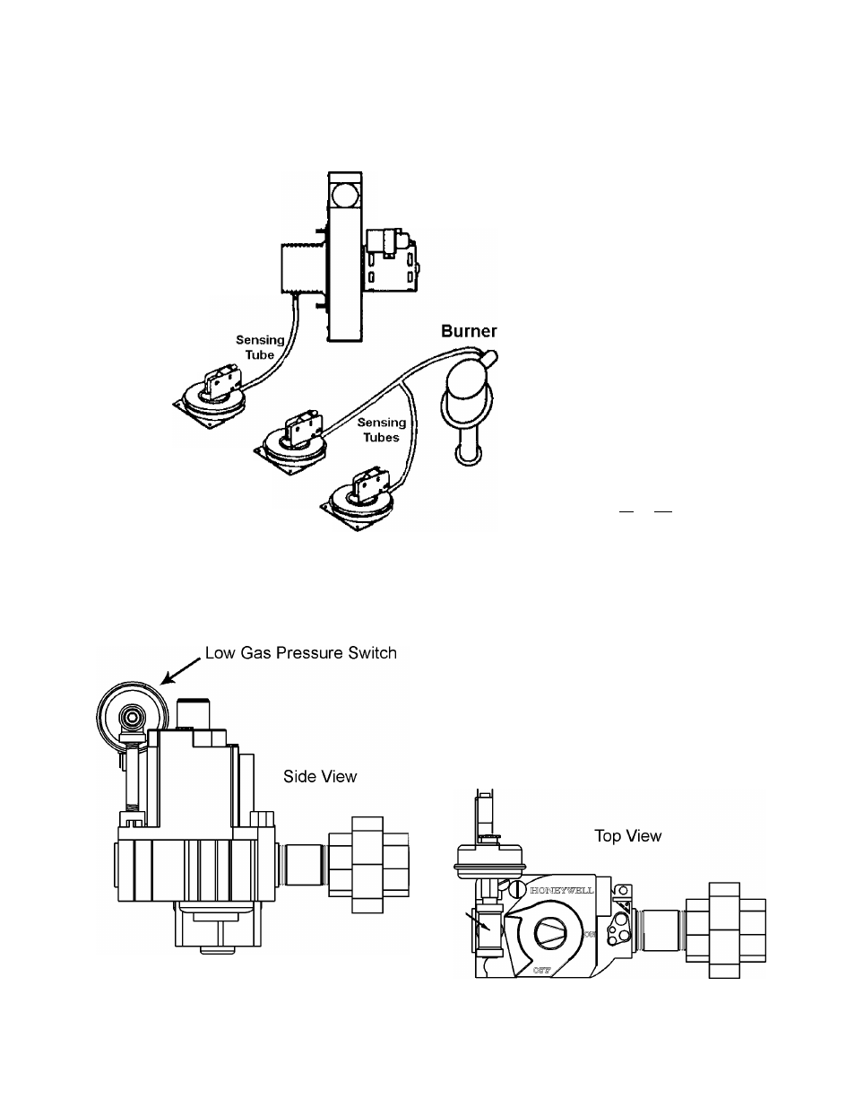
PRESSURE SWITCH LAYOUT
PRESSURE SWITCH WIRING
Notes:
Low Gas Pressure Switch
(BTH 120 a 250 only)
is installed on the inlet
side of the Gas Valve.
N.O. = Normally Open
N.C. = Normally Closed
Blower
Blocked Inlet Switch
N. C. Contacts
Blower Prover Switch
N. 0. Contacts
Blocked Outlet Switch
N. C. Contacts
LOW GAS
PRESSURE
BTH 120 & 250
(normally open)
.BLOCKED
I
OUTLET(FLUE)
(normally closed)
BLOWER
PROVER
(normally open)
.BLOCKED
I
INLET
(normally closed)
AA
AA
CN6 Plug
Control Board
GAS VALVE
I
Low Gas Pressure Switch
A. O. Smith Water Products Co.
Ashland City, Tennessee © 2004
35
Technical Training Department
TC-044 Revision 6