Notes, Bth muffler – A.O. Smith 960 through 967 User Manual
Page 40
Attention! The text in this document has been recognized automatically. To view the original document, you can use the "Original mode".
BTH S E R V I C E H A N D B O O K
S E R V I C E A I D S
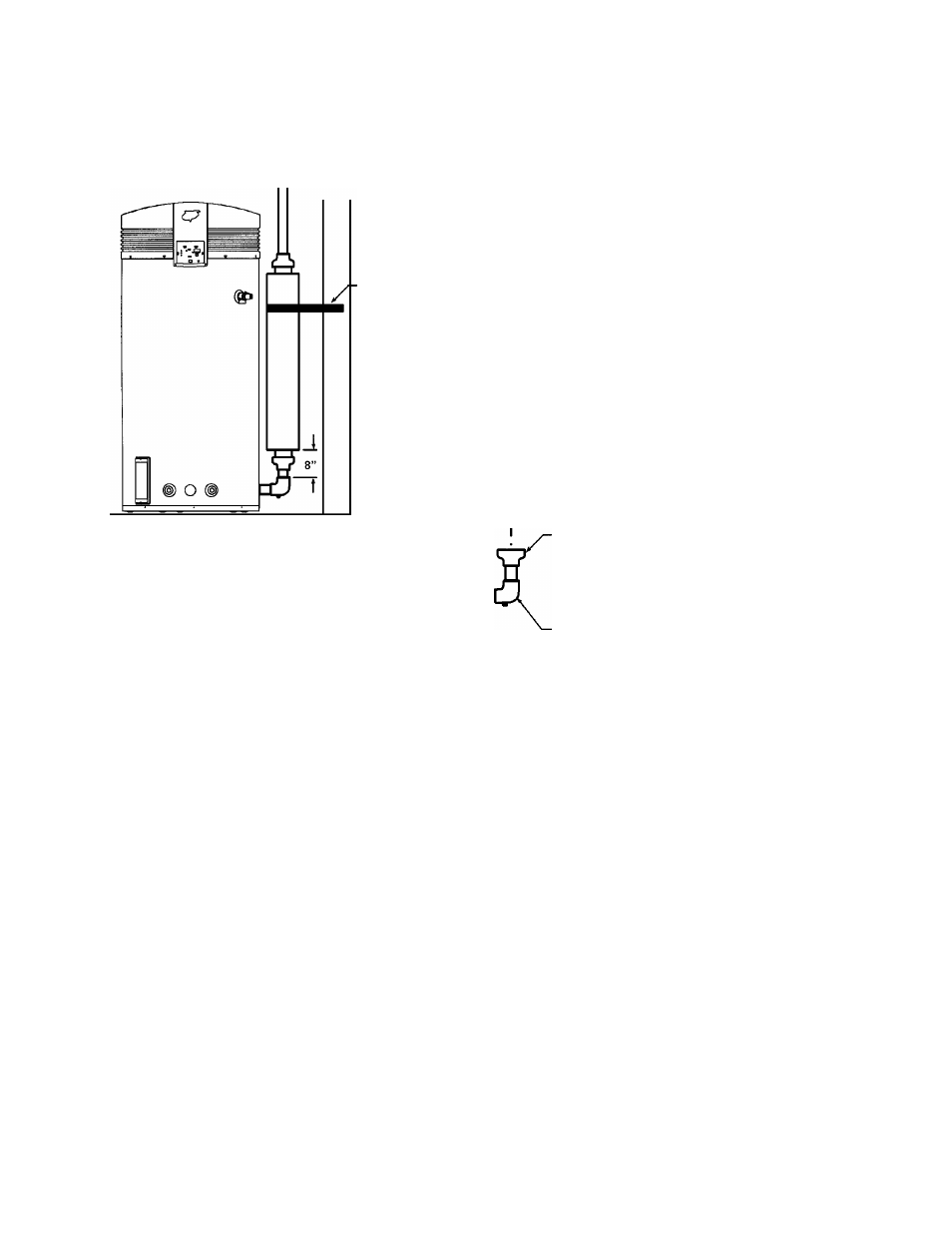
BTH MUFFLER
u
I
, 4”
X
3” PVC
REDUCING
COUPLING
4”
X
4” PVC
COUPLING
SUPPORT
(FIELD SUPPLIED)
4” PVC
I I
(BOTH ENDS) \fii
3” PVC
VENTING
8 5/8”
57
1
/
4
"
4” PVC
VENTING
I I
4”
X
3” PVC
REDUCING
COUPLING
(FIELD SUPPLIED)
4”
X
4” PVC .
COUPLING
(FIELD SUPPLIED)
HEATER CONDENSATE
ELBOW
NG
iUPPLIED)
I__I
_j^
N O T E S :
1. Install muffler in vertical position only.
2. Muffler must be a minimum of 8” from top of condensate elbow.
3. The muffler inlet and outlet are 4” PVC. If venting with a 4” PVC, a 4” x 4” PVC coupling (field
supplied) must be cemented to each end of the muffler. If venting with 3” PVC, a 4” x 3” PVC
reducing coupling (field supplied) must be cemented to each end of muffler (see illustration
above.)
4. Cement muffler into a location using ASTM D-2564 grade cement.
5. Secure muffler to suitable structure.
6. Operate heater through 1 heat cycle to ensure there are no exhaust leaks and there is no
obstruction of exhaust flow.
A. O. Smith Water Products Co.
Ashland City, Tennessee © 2004
39
Technical Training Department
TC-044 Revision 6