Pressure switch performance (continued), Pressure switch continuity test — operational – A.O. Smith 960 through 967 User Manual
Page 29
Attention! The text in this document has been recognized automatically. To view the original document, you can use the "Original mode".
BTH S E R V I C E H A N D B O O K
T R O U B L E S H O O T I N G
PRESSURE SWITCH PERFORMANCE (CONTINUED)
STEP 9B
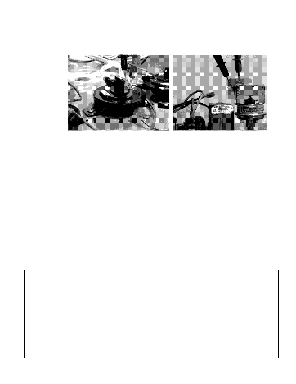
PRESSURE SWITCH CONTINUITY TEST — OPERATIONAL
Air pressure switches
Low gas pressure switch
STEP 9B: CHECK FOR CONTINUITY BETWEEN PRESSURE SWITCH TERMINALS WITH
WIRES REMOVED AND BLOWER RUNNING.
Condition:
• All wires are disconnected from all pressure switches — ends are taped off.
• On/Off switch is on.
• Call for heat is activated.
• Blower is running during trial for ignition.
• Multimeter is set to lowest ohms scale.
The wires disconnected are energized with 24 VAC from the control board. Do not allow these
wires to touch ground — use electrical tape to insulate wire connects during this test.
Check for continuity with an ohm meter between terminals on all pressure switches with the wires
removed and the blower running during a trial for ignition. Restart the water heater as needed.
The pressure switches are wired together in a “series” circuit. For the water heater to continue to
fire and satisfy a call for heat the control board must sense a closed pressure switch circuit.
IF...
THEN
continuity is not present between terminals on
one or more pressure switches — the switch
contacts are open.
compare the pressure reading recorded in Step
9A to the value given for that switch in the table
on page 36.
compare to value for correct Model and Series
number in table.
if the pressure recorded in Step 9A is within the value shown in
the table for the switch contacts to remain closed — replace the
pressure switch.
if the pressure recorded in Step 9A is not within the value shown
in the table for the switch contacts to remain closed — check for/
clear any restrictions in the vent and/or air intake piping, check
for an excessive number of elbows or equivalent feet of pipe
used in the vent and/or air intake piping.
check for/restore minimum supply gas pressure — Step13.
continuity is present.
continue to Step 10A.
Technical Training Department
TC-044 Revision 6
28
A. O. Smith Water Products Co.
Ashland City, Tennessee © 2004