Pressure switch continuity, Pressure switch continuity test, Step 7 – A.O. Smith 960 through 967 User Manual
Page 25
Attention! The text in this document has been recognized automatically. To view the original document, you can use the "Original mode".
BTH S E R V I C E H A N D B O O K
T R O U B L E S H O O T I N G
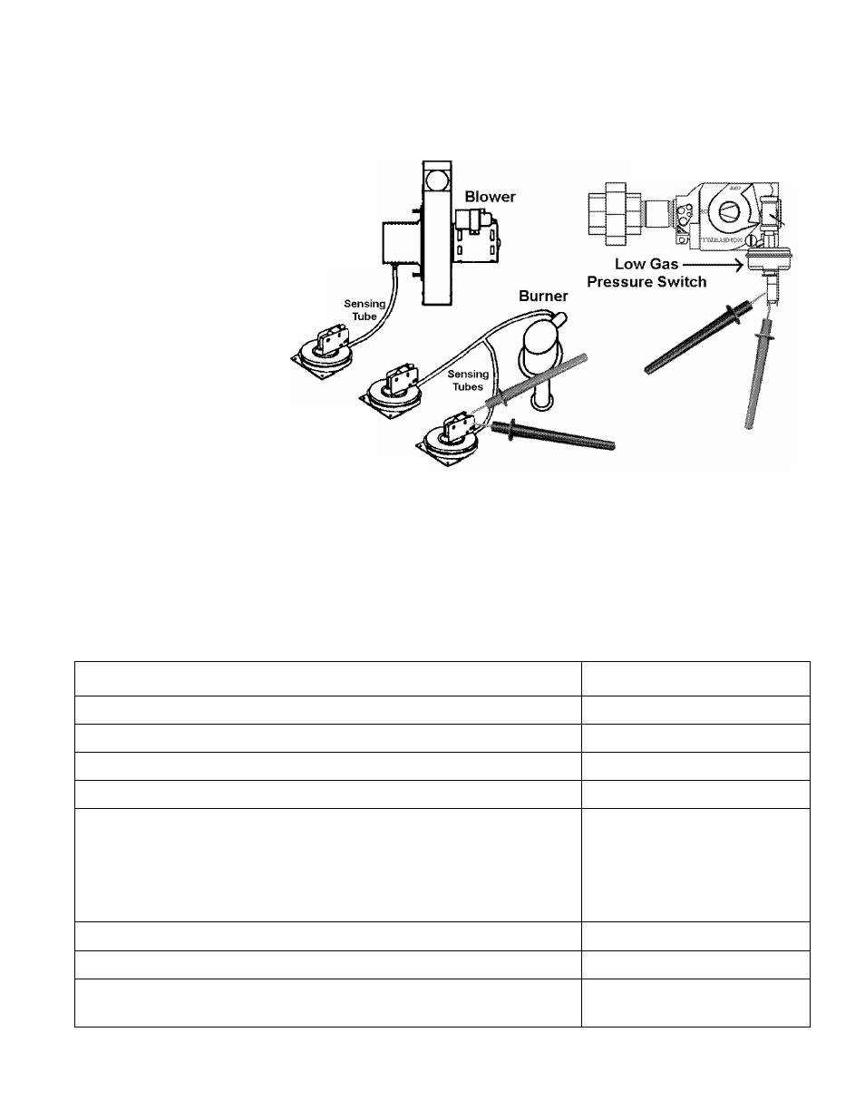
PRESSURE SWITCH CONTINUITY
STEP 7
PRESSURE SWITCH CONTINUITY TEST
Notes:
Low Gas Pressure Switch
(BTH 120 & 250 only)
is instailed on the iniet
side of the Gas Valve.
N.O. = Normally Open
N.C. = Normally Closed
Blocked Inlet Switch
N. C. Contacts
Gas Valve - Top View
Blower Prover Switch
N. O. Contacts
Blocked Outlet Switch
N. C. Contacts
STEP 7: CHECK FOR CONTINUITY BETWEEN PRESSURE SWITCH TERMINALS WITH
WIRES REMOVED.
Condition:
• On/Off switch is off.
• All wires are disconnected from all pressure switches.
• Multimeter is set to lowest ohms scale.
IF...
THEN
blocked inlet switch does not show continuity
replace switch.
blocked inlet switch does show continuity
continue.
blower proving switch does show continuity
replace switch.
blower proving switch does not show continuity
continue.
low gas pressure switch does not show continuity
check for minimum supply gas
pressure of
5.0” W.C. natural gas
9.0” W.C. LP gas
replace switch if gas pressures
are above these minimums.
low gas pressure switch does show continuity
continue.
blocked outlet pressure switch does not show continuity
replace switch.
blocked outlet pressure switch does show continuity
reconnect all wires to pressure
switches; continue to Step 8A.
Technical Training Department
TC-044 Revision 6
24
A. O. Smith Water Products Co.
Ashland City, Tennessee © 2004