Lower, Temperature probe plug, Ohms – A.O. Smith 960 through 967 User Manual
Page 24: Temperature probe, 6 temperature probe resistance
Attention! The text in this document has been recognized automatically. To view the original document, you can use the "Original mode".
BTH S E R V I C E H A N D B O O K
T R O U B L E S H O O T I N G
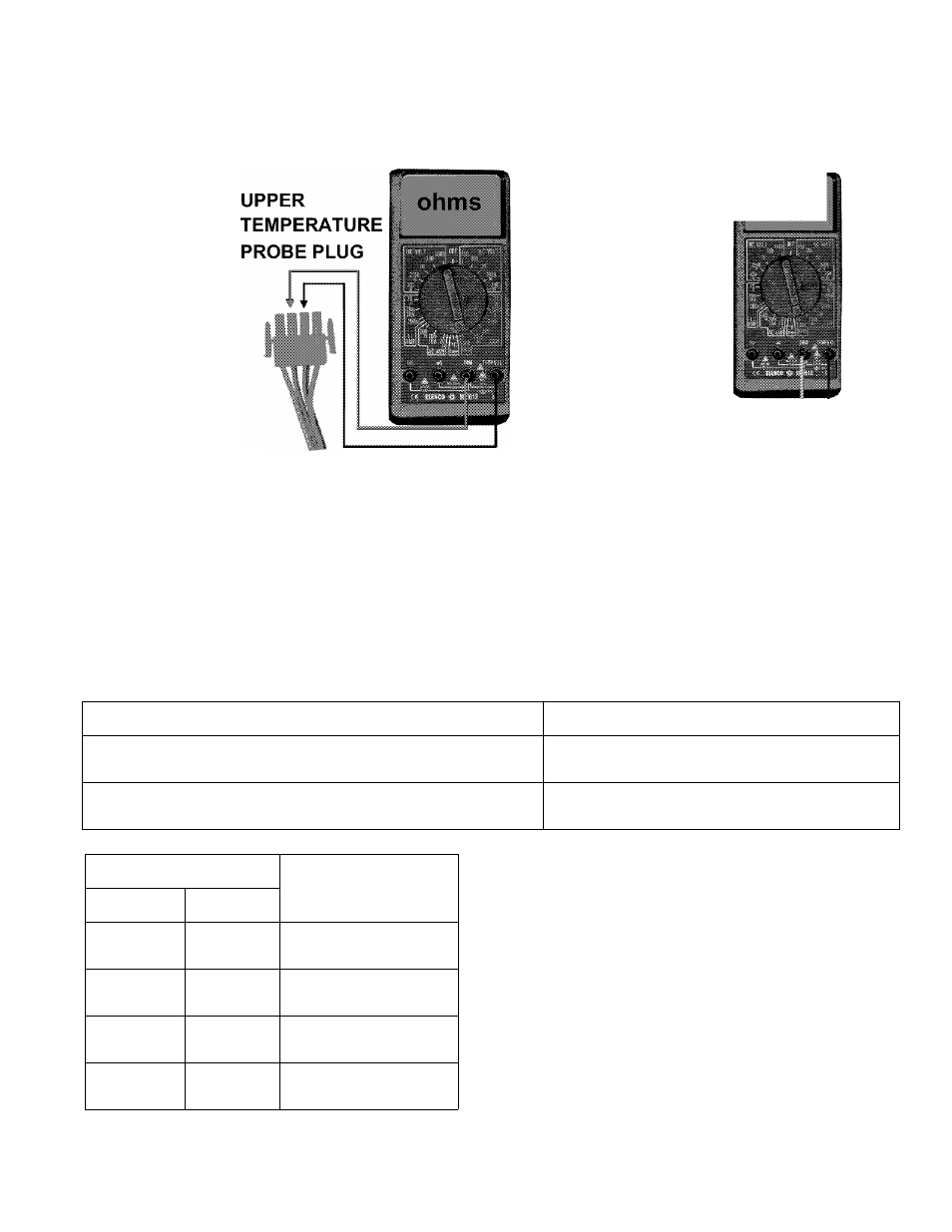
TEMPERATURE PROBE
STEP
6 TEMPERATURE PROBE RESISTANCE
LOWER
TEMPERATURE
PROBE PLUG
ohms
1
r
STEP 6: CHECK RESISTANCE OF THERMISTOR IN UPPER AND LOWER TEMPERATURE
PROBES.
Condition:
• Disconnect CN3 and CN8 plugs from control board.
• On/Off switch is off.
• Multimeter is set to lowest ohms scale above expected resistance.
Check resistance between black wire connects on CN3 and CN8 plugs as shown in illustration
above.
IF...
THEN
ohm reading does not approximately correspond to table at given
temperatures
replace temperature probe if thermistor is open,
shorted, or resistance value is off significantly.
ohm reading does approximately correspond to table at given
temperatures
continue to Step 7.
WATER TEMP
OHMS RESISTANCE
X
°F
3
40
26,435
21
70
11,974
37.5
100
5,862
49
120
3,780
54.5
130
3,066
60
140
2,503
71
160
1,698
82
180
1,177
NOTE: The upper and lower temperature probes contain
thermistors which are heat sensitive resistors. The control
board interprets changes in thermistor resistance as
changes in water temperature.
These thermistors are very reliable and should only be
replaced when:
The resistance test indicates an “open” (infinite resistance)
or a “direct short” (no resistance) circuit.
The nature of the service problem is temperature control
and the resistance readings are significantly off when com
pared to the values in the table here at the given tempera
ture.
A. O. Smith Water Products Co.
Ashland City, Tennessee © 2004
23
Technical Training Department
TC-044 Revision 6