Winco DGC-500 User Manual
Page 89
DGC-500 Installation
5-15
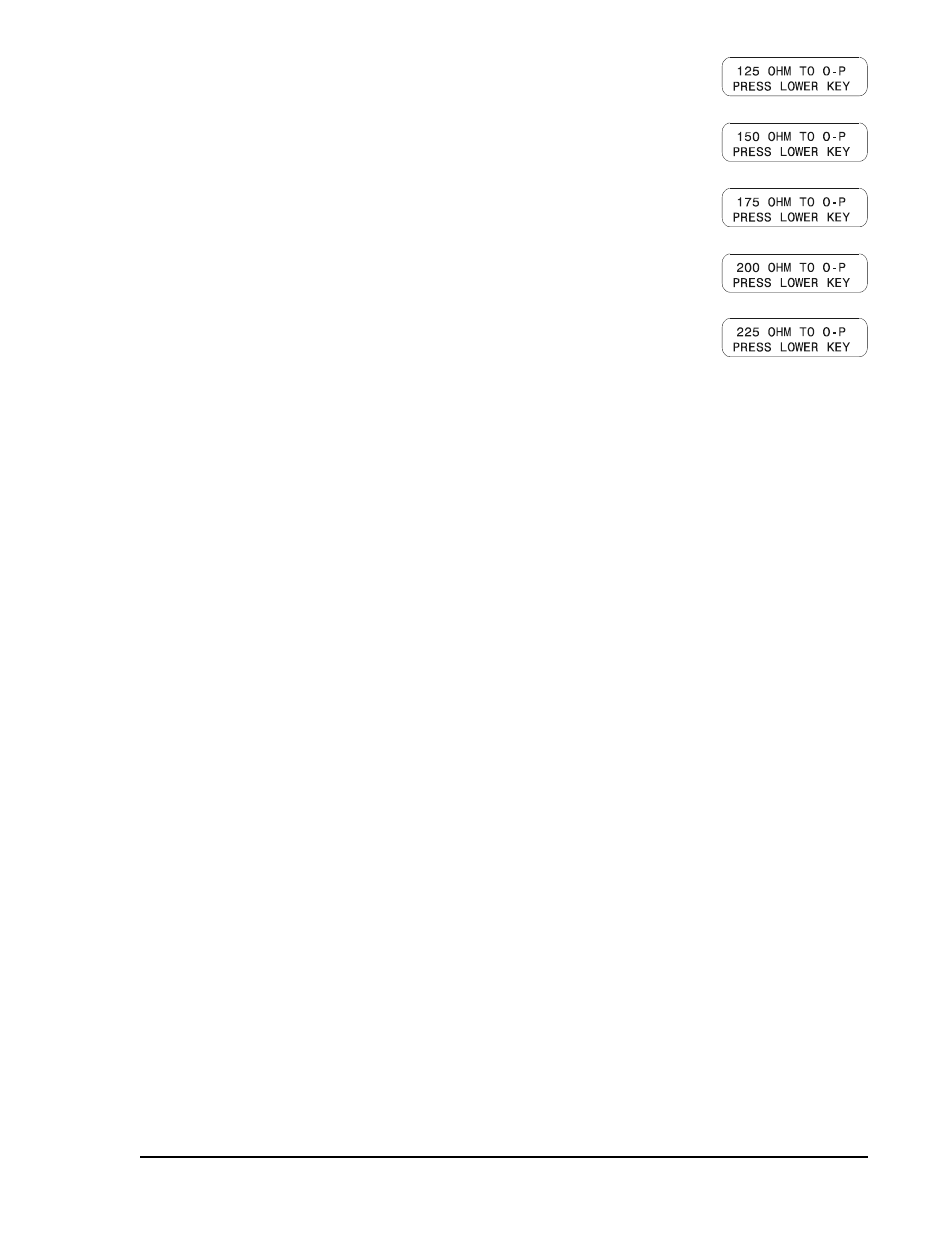
20. Press the Raise/Scroll pushbutton. The screen at right is displayed.
Connect a resistance of 125 ohms across the oil pressure sender input (P13
and P19). Press the Lower/Scroll pushbutton.
21. Press the Raise/Scroll pushbutton. The screen at right is displayed.
Connect a resistance of 150 ohms across the oil pressure sender input (P13
and P19). Press the Lower/Scroll pushbutton.
22. Press the Raise/Scroll pushbutton. The screen at right is displayed.
Connect a resistance of 175 ohms across the oil pressure sender input (P13
and P19). Press the Lower/Scroll pushbutton.
23. Press the Raise/Scroll pushbutton. The screen at right is displayed.
Connect a resistance of 200 ohms across the oil pressure sender input (P13
and P19). Press the Lower/Scroll pushbutton.
24. Press the Raise/Scroll pushbutton. The screen at right is displayed.
Connect a resistance of 225 ohms across the oil pressure sender input (P13
and P19). Press the Lower/Scroll pushbutton.
After step 24 is completed successfully and the Raise/Scroll pushbutton is pressed, the INPUT CALIBRATE
FUNCTION screen appears and signals that calibration is complete.