Preflight, Channel radio setup – Top Flite TOPA0145 User Manual
Page 43
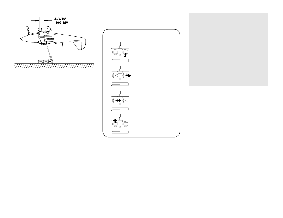
❏ 3. With the wing attached to the fuselage, the
landing gear extended (if you have retracts) and an
empty fuel tank, lift the model at the balance point or
place it on your C.G. Machine
™
(shown in the sketch).
If the tail drops, the model is tail heavy and you must
relocate your battery pack or other components
forward or add weight to the nose. If the nose drops,
it is nose heavy and you must relocate your battery
pack or other components aft or add weight to the tail.
In order to save weight, relocate your battery pack
and/or receiver or other components before you add
additional weight to arrive at the correct C.G. You
may install nose or tail weight by gluing lead weights
inside the fuselage where necessary.
Note: The amount of weight required will depend on
the engine, density of the wood provided and how
heavily or lightly the tail was built.
Final hookups and checks
❏ 1. Take the servo arms off the servos, turn on the
transmitter and center all the trims. Reinstall all the
servo arms and secure them with the screws.
❏ 2. Double-check all the servos and make sure the
servo arms are secure and all the clevises have a
silicone retainer.
❏ 3. Make sure the control surfaces move in the
proper direction as illustrated in the following sketch.
❏ 4. Adjust your pushrod hookups and set up your
radio to provide the control surface movements as
follows. Use a ruler or a Great Planes Accu Throw
™
Control Surface Deflection Meter (GPMR2405) to
measure the throws.
The balance point and control surface throws listed
in this manual are the ones at which the P-39 flies
best. Set up your aircraft to those specifications. If,
after a few flights, you would like to adjust the throws
or C.G. to suit your tastes, that is fine. Too much
control surface throw can make your model difficult
to control or force it into a stall, so remember...More
is not better.
PREFLIGHT
Identify your model
Regardless if you fly at an AMA sanctioned R/C club
site or if you fly somewhere on your own, you should
always have your name, address, telephone number
and AMA number on or inside your model. It is
required at all AMA R/C club flying sites and AMA
sanctioned flying events.
Charge the batteries
Follow the battery charging procedures in the radio
instruction manual. Always charge your transmitter and
receiver batteries the night before you go flying and at
other times as recommended by the radio manufacturer.
Balance the propellers
Carefully balance your propellers before you fly. An
unbalanced prop is the single most significant cause
of vibration that can damage your model. Not only
will engine mounting screws and bolts loosen,
possibly with disastrous effect, but vibration may
also damage your radio receiver and battery.
Vibration can also cause the fuel to foam, which will,
in turn, cause the engine to run hot or quit.
Recommended Control Surface Throws
Low Rate
High Rate
Aileron
3/8" up
5/8" up
3/8" down
5/8" down
[9.5mm]
[15.9mm]
Elevator
5/16" up,
1/2" up
5/16" down
1/2" down
[7.9mm]
[12.7mm]
Rudder
1" left,
1-1/2" left
1" right
1-1/2 down
[25.4mm]
[38mm]
Flaps
2" down [51mm]
CARBURETOR WIDE OPEN
RUDDER MOVES RIGHT
LEFT AILERON MOVES DOWN
RIGHT AILERON MOVES UP
ELEVATOR MOVES UP
4-CHANNEL
TRANSMITTER
(STANDARD MODE 2)
4-CHANNEL RADIO SETUP
TRANSMITTER
4-CHANNEL
TRANSMITTER
4-CHANNEL
TRANSMITTER
4-CHANNEL
43