Top Flite TOPA0145 User Manual
Page 21
❏ 6. Test fit formers F1A, F3A and F6A to the wing
saddle. The formers and saddle have been notched
to allow the structure to interlock together. When you
assemble this structure, the longer wing saddle
should be on the left side of the assembly.
Remember, you are building this upside down. Make
sure that you have the longer wing saddle on what
will be the left side of the fuselage.
❏ 7. Both formers must be square to the saddles.
When you are satisfied with the fit, glue F3A and F6A
to the saddles with CA.
❏ 8. Glue F1A to the saddle using 30-minute epoxy.
Set the saddle assembly aside to dry.
❏ 9. When the epoxy in the saddle assembly has
cured, test fit the saddle assembly to the fuselage.
❏ 10. When you are satisfied with the fit, glue it
permanently in place onto the fuselage. This should
be done with 5-minute epoxy and some weights to
hold it in place. Allow the epoxy to cure.
❏ 11. Locate the 1/8" x 2-3/4" x 2-3/4"[3.2 x 70 x
70mm] firewall backplate. Glue it to the back of F1
and F1A with 5-minute epoxy. Locate it as shown on
the plan.
❏ 12. Glue two F4A formers and two F5A formers to
each side of the wing saddle as shown on the plan.
Glue former F2A in place as shown on the plan.
❏ 13. Glue formers F7A, F8A, F9A and F10A into
position as shown on the plan. Be sure that they are
straight when you glue them in place. Do not glue
F6AD in position yet.
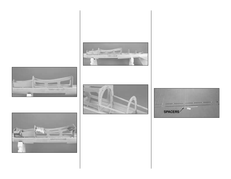
❏ 14. Temporarily place two balsa side stringers in
position as shown in the photograph. This will give
you the position for gluing F6AD in place. When
satisfied with the fit, glue F6AD to F6A, and remove
the stringers.
Install the Pushrods
❏ 15. Before we close the rest of the fuselage, this
would be a good time to position the pushrods and
servo mounting rails. Locate a 1/4" x 3/8" x 36"
[6.4 x 9.5 x 914mm] basswood stick and cut four
pieces as shown on the plan to fit the fuselage.
These become the servo mounting rails.
❏ 16. Glue the servo mounting rails into position as
shown on the plan (See photo at Step 21.)
❏ 17. Cut a plastic pushrod outer tube to length for
the elevator and put it in place. This tube should go
through the hole that you previously drilled in F9.
Roughen the tube with sandpaper in the areas where
the tubes will be glued.
❏ 18.Mark the rudder pushrod exit on the left side of
the fuse where shown on the fuselage plan. Drill a
3/16" [4.8mm] hole on the mark. Angle the drill
approximately 25 degrees when drilling on the mark.
This will allow the pushrod to exit the fuse at the
correct angle
❏ 19. Cut the plastic pushrod outer tube to length for
the rudder. Roughen the tube with 150 grit
sandpaper where it will be glued to the wood. Glue
the tube in position through the hole you just drilled
in the side of the fuselage.
❏ 20. Cut the .074 wire pushrods to length for each
of the control surfaces. Clean residual oil from the
pushrod wire with a cloth dampened with alcohol or
other solvent. Cut six 3/8” spacers from the white
inner pushrod tube, then slide them, evenly spaced,
onto the wire. Make sure you position the bushings
at the ends of the wire so they will not protrude from
the guide tube, or the controls could become
jammed during flight. If the spacers slide easily onto
the wire, secure them with a drop of thin CA (make
sure the CA sets before you slide the pushrod into
the guide tube!). If the spacers are difficult to slide
on, cut them to a shorter length so they will be a little
easier to slide onto the wire.
21