Top Flite TOPA0145 User Manual
Page 15
BUILD THE FUSELAGE
Frame the Fuselage top
❏ 1. Cut the fuselage plan on the dashed lines and
tape the fuse top view to your building board. Cover
the plan with Plan Protector.
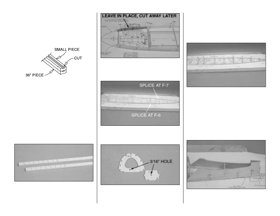
❏ 2. Gather the three 3/16" x 3/8" x 36" [4.8 x 9.5 x
914mm] grooved main stringers. Cut one of the
stringers into two pieces. One piece will be 20-3/4"
[527mm] long; the other piece, 15-1/4" [387.5] long.
Place the 20-3/4 " [527mm] long main stringer on top
of the 36" [914mm] main stringer so the ends align.
Cut the stringers and position them so that the left
side main stringer has the splice at former F6. Do the
same thing with the 15-1/4" [394mm] main stringer
on the right side but with the splice location at F7.
The splice locations are noted on the top view of the
plan. Cut, splice and glue them together at an
approximately 45-degree angle as shown in the
sketch (use your miter box if you have one).
❏ 3. Use a razor saw to cut small v-notches, 3/32"
[2.4mm] deep in the inside of the 36" [914mm]
stringer. Do this in the area that will be glued between
the nose ring and F1. This will allow the stringers to
conform to the shape as shown on the plan.
❏ 4. You will notice that the right side main stringer
gets cut away forward of F1. Leave it in place for
now. This will help to secure the nose ring as we
begin the process of framing the fuselage.
❏ 5. Pin the two stringers to the plan so the left side
main stringer is spliced at F6 and the right side main
stringer is at F7 as shown on the plan.
❏ 6. Refer to the Pushrod Locations area on the fuse
plan and drill 3/16" [4.8mm] holes through the punch
marks in the die-cut 1/8" [3.2mm] plywood formers
F8 and F9. One hole in F8, two in F9.
❏ 7. Locate the two formers F1 and F1A. Using
6-minute epoxy, glue the two F1 formers together
and then the two F1A formers and set them aside
to dry. Do not glue the F1 and F1A formers together
at this time.
❏ 8. Test fit all die-cut 1/8" [302mm] plywood formers
(F2 through F10) to the main stringers over their
locations on the plan. You may need to bevel the
notches in some of the rear formers to accommodate
the angle at which they join the main stringers. Use a
small square to make sure the formers are vertical
and glue them to the main stringers. Don't be
concerned if the formers are slightly warped. You will
be able to straighten them when you add the stringers.
❏ 9. Test fit and then glue the Stab Saddles into
position over the main stringers and to former F9
and F10.
15