Top Flite TOPA0145 User Manual
Page 12
❏ ❏ 2. Cut a 1/4" x 3/4" x 30" [6.4 x 19.1 x 762mm]
balsa stick to the length shown on the plan for the
elevator leading edge. Use a straightedge to draw
a center line the length of the elevator leading edge.
Glue the elevator core to the LE directly on top of the
line so that the core will be centered on the LE. Use
a square to make sure you glue the LE perpendicular
to the elevator core.
Hint: Place a 1/4" [6.4mm] piece of balsa under the
square to raise it to the level of the LE.
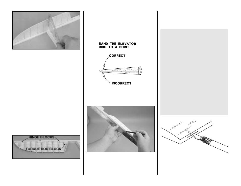
❏ ❏ 3. Make the elevator hinge blocks from a 1/4"
x 5/16" x 24" [6.4 x 7.9 x 610mm] balsa stick. Glue
the hinge blocks to the elevator as shown on the plan
(Do this for the top and bottom of the elevator core).
See photo at step 5.
❏ ❏ 4. Make the elevator torque rod blocks from
1/4" x 5/16" x 24" [6.4 x 7.9 x 610mm] balsa. Glue the
blocks to the elevator as shown on the plan. (Do this
for the top and bottom of the elevator core.) See
photo at step 5.
❏ ❏ 5. Use four 1/16" x 5/16" x 24" [6.4 x 7.9 x
610mm] balsa sticks to make the elevator ribs. Cut
the sticks to the correct length, then glue them to the
elevator core and the leading edge of the elevator.
❏ ❏ 6. Use a piece of leftover 1/16" [1.6mm]
sheeting to make the elevator root cap. Glue the
root cap into position.
❏ ❏ 7. Place the elevator on the stab TE and shape
the elevator LE to match the shape of the stab TE.
❏ ❏ 8. Proceed slowly and carefully, shaping the
elevator ribs and the hinge blocks to match the
elevator LE and the cross section on the plan.
❏ ❏ 9. Insert two T-pins through the center of one of
the elevator LE, near the tip and near the root. Place
a straightedge across the T-pins and draw the
centerline on the elevator LE with a ballpoint pen.
Draw a centerline along the TE of the stab the
same way.
❏ 10. Carefully cut away the center section of the
elevator leading edge so the elevators match the
shape as shown on the plan. Note which elevator
matches which side of the stab.
❏ ❏ 11. Mark the location of the hinge slots on the
elevator and stab where shown on the plan. With a
#11 blade, cut the hinge slots in the elevator and the
stab along the centerlines you marked earlier.
AND #11 BLADE
WITH HOBBY KNIFE
CUT HINGE SLOT
IMPORTANT NOTES ABOUT CA HINGES
This kit is supplied with a CA hinge material
consisting of a 3-layer lamination of Mylar and
polyester. It is specially made for hinging model
airplane control surfaces. When properly
installed, this type of CA hinge provides the best
combination of strength, durability and easy
installation. We trust all of our Gold Edition war
birds to these hinges, but it is essential to install
them correctly. Carefully follow the hinging
instructions in this manual for the best result.
The most common mistake made by modelers
when installing CA hinges is making the hinge
slots too tight restricting the flow of CA to the back
of the hinges; or not using enough glue to fully
secure the hinge over its entire surface area. This
results in hinges that are only tack glued into the
hinge slots. The techniques for cutting the hinge
slots and gluing in CA hinges (near the end of the
manual) have been developed to ensure thorough
and secure gluing.
12